Community project
ESP32 Talking Face Assistant
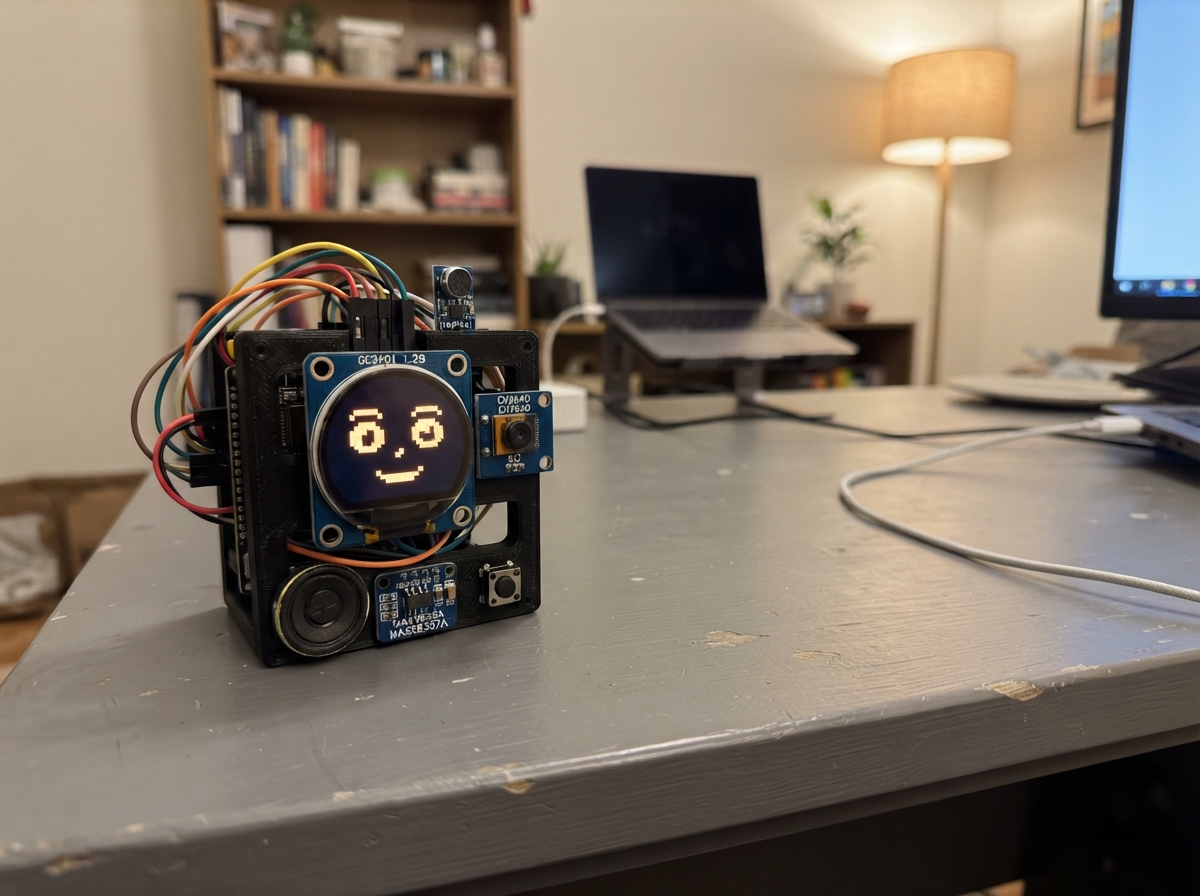
Build an interactive talking face assistant powered by an ESP32 that displays expressive eyes on a round 1.28-inch LCD screen, listens for voice commands through an I2S microphone, and responds with audio through a speaker. The assistant features animated blinking, color-changing eyes that turn yellow when listening, and a camera for vision capabilities.
This guide provides a complete wiring diagram, parts list, and step-by-step assembly instructions to connect the round TFT display, INMP441 microphone module, MAX98357A amplifier, OV2640 camera, and push button to your ESP32. You'll also get the Arduino firmware needed to bring the animated face to life with real-time eye animations and audio I/O handling.
Wiring diagram

Gather all the parts
Assemble it in 6 steps
1. Keep the XIAO unpowered while wiring
Place the Seeed Studio XIAO ESP32S3, round screen, camera, microphone, amplifier, speaker, and push button on a non-metal surface. Leave the USB-C cable unplugged until every wire is checked.
- The XIAO is small: use the printed GPIO number on the board or its solder pads, not the old DevKit pin positions.
- Use short jumper wires for the camera and round screen so their signals stay reliable.
- Do not connect or move wires while USB-C power is plugged in; a loose wire can touch the wrong pin and damage a module.
2. Wire the round face screen
Connect the GC9A01 round screen: VCC to 3V3 (power), GND to GND (ground), MOSI or DIN to GPIO11 (picture data), SCK or CLK to GPIO12 (clock), CS to GPIO10 (screen select), DC to GPIO13 (picture command/data choice), RST to GPIO14 (screen reset), and BL or BLK to 3V3 (backlight power).
- Some modules print DIN instead of MOSI and CLK instead of SCK; these names mean the same connections here.
- Make sure VCC and GND are not swapped — swapped power can damage the round screen.
3. Wire the camera
Connect the camera: 3V3 to 3V3 (power), GND to GND (ground), SDA to GPIO8 (camera setup data), SCL to GPIO9 (camera setup clock), XCLK to GPIO1 (camera clock), PCLK to GPIO2 (pixel timing), D0 to GPIO4, D1 to GPIO5, D2 to GPIO6, D3 to GPIO7, D4 to GPIO38, D5 to GPIO39, D6 to GPIO40, D7 to GPIO41 (picture data), VSYNC to GPIO42 (frame timing), and HREF to GPIO47 (line timing).
- Keep the camera lens clear and do not press on its small sensor board.
- This wiring assumes an OV2640 breakout with the printed pins named exactly as listed; do not guess pin names on a different camera module.
4. Wire the microphone and speaker amplifier
Connect the INMP441 microphone: VDD to 3V3 (power), GND to GND (ground), SCK to GPIO15 (shared sound clock), WS to GPIO16 (shared sound timing), SD to GPIO17 (microphone sound data), and L/R to GND (left-channel choice). Connect the MAX98357A amplifier: VIN to 3V3 (power), GND to GND (ground), BCLK to GPIO15 (shared sound clock), LRC to GPIO16 (shared sound timing), and DIN to GPIO18 (sound data sent to the speaker).
- GPIO15 and GPIO16 deliberately go to both sound modules; they are shared timing wires, not accidental duplicates.
- Use only the amplifier for the speaker — connecting a speaker straight to an ESP32 pin can damage the board.
5. Connect the speaker and talk button
Connect MAX98357A SPK+ to the speaker POS terminal (sound output) and MAX98357A SPK- to the speaker NEG terminal (sound output). Connect the push button GND to GND (ground) and SIGNAL to GPIO21 (button signal).
- If the speaker has no plus mark, either way is safe for this single speaker; keep the two wires paired and do not connect either speaker wire to GND.
- The amplifier speaker terminals are a pair of driven outputs, not power and ground; never connect SPK- to GND.
6. Power and try the assistant
Inspect every power and ground wire once more, then plug the XIAO ESP32S3 into USB-C. The round screen should show a blinking face. Press the button once to have it take a camera frame, show a listening face, and play a three-note greeting through the speaker.
- If the face is dark, check the BL or BLK wire goes to 3V3 and confirm the display controller is GC9A01 or GC9A01A.
- If anything becomes hot or you smell heated plastic, unplug USB-C immediately and re-check the power wires.
Review all connections
1. Connections between "voice_mic" and "ESP32"
2. Connections between "speaker_amp" and "ESP32"
3. Connections between "talk_button" and "ESP32"
4. Connections between "camera" and "ESP32"
5. Connections between "face_display" and "ESP32"
Deploy the firmware
#include <Arduino.h>
#include <SPI.h>
#include <Adafruit_GFX.h>
#include <Adafruit_GC9A01A.h>
#include <driver/i2s.h>
#include <esp_camera.h>
#include <math.h>

#define TFT_CS 10
#define TFT_DC 13
#define TFT_RST 14
#define I2S_BCLK 15
#define I2S_LRCLK 16
#define I2S_MIC_DATA 17
#define I2S_SPK_DATA 18
#define BUTTON_PIN 21
#define CAM_XCLK 1
#define CAM_PCLK 2
#define CAM_D0 4
#define CAM_D1 5
#define CAM_D2 6
#define CAM_D3 7
#define CAM_D4 38
#define CAM_D5 39
#define CAM_D6 40
#define CAM_D7 41
#define CAM_VSYNC 42
#define CAM_HREF 47
#define CAM_SDA 8
#define CAM_SCL 9

const uint16_t COLOR_BLACK = 0x0000;
const uint16_t COLOR_WHITE = 0xFFFF;
const uint16_t COLOR_NAVY = 0x000F;
const uint16_t COLOR_CYAN = 0x07FF;
const uint16_t COLOR_YELLOW = 0xFFE0;

Adafruit_GC9A01A tft(TFT_CS, TFT_DC, TFT_RST);
bool cameraReady = false;
bool eyesClosed = false;
bool listening = false;
unsigned long lastBlinkMs = 0;
unsigned long lastFaceMs = 0;
unsigned long lastButtonMs = 0;

void drawFace(bool closed, bool isListening) {
  const uint16_t eyeColor = isListening ? COLOR_YELLOW : COLOR_CYAN;
  tft.fillScreen(COLOR_BLACK);
  tft.fillCircle(120, 120, 116, COLOR_NAVY);
  tft.drawCircle(120, 120, 115, COLOR_CYAN);
  if (closed) {
    tft.fillRoundRect(48, 88, 48, 7, 3, eyeColor);
    tft.fillRoundRect(144, 88, 48, 7, 3, eyeColor);
  } else {
    tft.fillRoundRect(47, 61, 50, 64, 22, eyeColor);
    tft.fillRoundRect(143, 61, 50, 64, 22, eyeColor);
    tft.fillCircle(72, 93, 14, COLOR_BLACK);
    tft.fillCircle(168, 93, 14, COLOR_BLACK);
  }
  tft.drawLine(82, 146, 94, 157, COLOR_WHITE);
  tft.drawLine(94, 157, 120, 163, COLOR_WHITE);
  tft.drawLine(120, 163, 146, 157, COLOR_WHITE);
  tft.drawLine(146, 157, 158, 146, COLOR_WHITE);
  tft.setTextColor(COLOR_WHITE, COLOR_NAVY);
  tft.setTextSize(2);
  if (isListening) {
    tft.setCursor(48, 190);
    tft.print("Listening");
  } else if (cameraReady) {
    tft.setCursor(58, 190);
    tft.print("Hello!");
  } else {
    tft.setCursor(45, 190);
    tft.print("Camera?");
  }
}

bool startCamera() {
  camera_config_t config = {};
  config.ledc_channel = LEDC_CHANNEL_0;
  config.ledc_timer = LEDC_TIMER_0;
  config.pin_d0 = CAM_D0; config.pin_d1 = CAM_D1;
  config.pin_d2 = CAM_D2; config.pin_d3 = CAM_D3;
  config.pin_d4 = CAM_D4; config.pin_d5 = CAM_D5;
  config.pin_d6 = CAM_D6; config.pin_d7 = CAM_D7;
  config.pin_xclk = CAM_XCLK; config.pin_pclk = CAM_PCLK;
  config.pin_vsync = CAM_VSYNC; config.pin_href = CAM_HREF;
  config.pin_sscb_sda = CAM_SDA; config.pin_sscb_scl = CAM_SCL;
  config.pin_pwdn = -1; config.pin_reset = -1;
  config.xclk_freq_hz = 20000000;
  config.pixel_format = PIXFORMAT_GRAYSCALE;
  config.frame_size = FRAMESIZE_QQVGA;
  config.jpeg_quality = 12;
  config.fb_count = 1;
  config.grab_mode = CAMERA_GRAB_LATEST;
  return esp_camera_init(&config) == ESP_OK;
}

void startAudio() {
  i2s_config_t config = {};
  config.mode = (i2s_mode_t)(I2S_MODE_MASTER | I2S_MODE_TX | I2S_MODE_RX);
  config.sample_rate = 16000;
  config.bits_per_sample = I2S_BITS_PER_SAMPLE_32BIT;
  config.channel_format = I2S_CHANNEL_FMT_RIGHT_LEFT;
  config.communication_format = I2S_COMM_FORMAT_STAND_I2S;
  config.dma_buf_count = 6;
  config.dma_buf_len = 64;
  config.tx_desc_auto_clear = true;
  i2s_pin_config_t pins = {};
  pins.bck_io_num = I2S_BCLK;
  pins.ws_io_num = I2S_LRCLK;
  pins.data_out_num = I2S_SPK_DATA;
  pins.data_in_num = I2S_MIC_DATA;
  i2s_driver_install(I2S_NUM_0, &config, 0, nullptr);
  i2s_set_pin(I2S_NUM_0, &pins);
  i2s_zero_dma_buffer(I2S_NUM_0);
}

void playGreeting() {
  const int sampleRate = 16000;
  const int noteSamples = sampleRate / 5;
  const float notes[] = {523.25f, 659.25f, 783.99f};
  int32_t frame[2];
  for (float frequency : notes) {
    for (int i = 0; i < noteSamples; ++i) {
      const float wave = sinf(2.0f * PI * frequency * i / sampleRate);
      const int32_t sample = (int32_t)(wave * 180000000.0f);
      frame[0] = sample; frame[1] = sample;
      size_t written = 0;
      i2s_write(I2S_NUM_0, frame, sizeof(frame), &written, portMAX_DELAY);
    }
  }
}

int microphoneLevel() {
  int32_t frames[32];
  size_t bytesRead = 0;
  if (i2s_read(I2S_NUM_0, frames, sizeof(frames), &bytesRead, 5 / portTICK_PERIOD_MS) != ESP_OK || bytesRead == 0) return 0;
  int64_t total = 0;
  const size_t count = bytesRead / sizeof(int32_t);
  for (size_t i = 0; i < count; ++i) total += llabs((int64_t)frames[i]);
  return (int)(total / count / 1000000);
}

void setup() {
  pinMode(BUTTON_PIN, INPUT_PULLUP);
  SPI.begin(12, -1, 11, TFT_CS);
  tft.begin();
  tft.setRotation(0);
  drawFace(false, false);
  startAudio();
  cameraReady = startCamera();
  drawFace(false, false);
}

void loop() {
  const unsigned long now = millis();
  const bool shouldListen = microphoneLevel() > 25;
  if (shouldListen != listening && now - lastFaceMs > 200) {
    listening = shouldListen;
    drawFace(eyesClosed, listening);
    lastFaceMs = now;
  }
  if (now - lastBlinkMs > 3500) {
    eyesClosed = true;
    drawFace(true, listening);
    delay(120);
    eyesClosed = false;
    drawFace(false, listening);
    lastBlinkMs = now;
    lastFaceMs = now;
  }
  if (digitalRead(BUTTON_PIN) == LOW && now - lastButtonMs > 600) {
    lastButtonMs = now;
    listening = true;
    drawFace(false, true);
    if (cameraReady) {
      camera_fb_t *frame = esp_camera_fb_get();
      if (frame != nullptr) esp_camera_fb_return(frame);
    }
    playGreeting();
    listening = false;
    drawFace(false, false);
  }
  delay(10);
}
Remix this project
Make it yours in one click
Open a full copy of this project in your own Schematik workspace — diagram, code, parts, and assembly steps included. Swap the sensor, add features, or redesign the whole thing with AI. The author's original stays untouched.