Community project
Feather Hexapod Spider
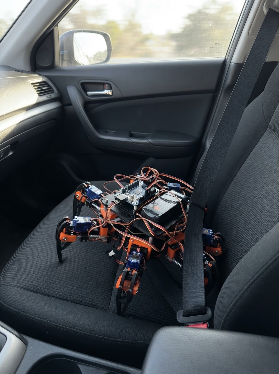
Build a six-legged robotic spider that walks using coordinated servo motion. The hexapod is powered by twelve MG90S micro servos controlled through a PCA9685 PWM driver, with a dedicated servo battery pack and UBEC regulator ensuring clean power delivery to all components.
This guide provides a complete wiring diagram, parts list, and Arduino firmware with tripod gait walking logic. Assembly covers building the spider frame, establishing safe power paths, connecting all servo channels, and calibrating each leg for smooth, synchronized locomotion.
Wiring diagram

Gather all the parts
Assemble it in 5 steps
1. Make the small spider body
Use a light plastic, plywood, or 3D-printed body about 10 to 14 cm long. Mount six hip servos around its edge: left front, left middle, left rear, right front, right middle, and right rear. Attach the second servo and a short leg link to each hip servo, but leave every servo horn screw loose for now.
- Keep the battery low and near the middle of the body so the robot is less likely to tip over.
- Use identical left and right leg links if possible; uneven legs make walking difficult.
- Do not force a servo shaft by hand while it has power; that can strip its small gears.
2. Wire the Feather to the servo driver
With all power disconnected, connect the Feather's 3V3 pin to the PCA9685 VCC terminal (logic power), Feather GND to PCA9685 GND (shared ground), Feather SDA/D2 to PCA9685 SDA (data), and Feather SCL/D3 to PCA9685 SCL (clock). Leave the PCA9685 OE terminal unconnected because this style of board holds it enabled by default.
- Use four short jumper wires and keep SDA and SCL away from the thick motor-power wires.
- The PCA9685 VCC terminal is not the same terminal as V+; VCC is the small logic-power connection.
- Make sure the PCA9685 VCC and GND wires are not swapped — swapped power can damage the driver board.
3. Build the safe motor power path
Connect the battery POSITIVE lead to the UBEC VIN+ terminal (battery input) and battery NEGATIVE to UBEC VIN- (battery return). Connect UBEC VOUT+ to the 5V rail that feeds PCA9685 V+ and every servo red wire (motor power). Connect UBEC VOUT- to the shared ground rail that feeds PCA9685 GND and every servo brown or black wire (ground). Feed the Feather from this regulated 5 V output through its USB power input using a suitable 5 V USB lead or a protected 5 V USB power adapter connection; do not connect the 6 V battery directly to the Feather.
- Use thicker wire for battery, regulator output, and the shared servo power rails; these wires carry much more current than the signal wires.
- Before plugging in the Feather, measure the UBEC output if you have a meter: it must be close to 5 V.
- A 12-servo robot can draw several amps when a leg is stuck. A weak supply, thin wires, or loose power connection can cause sudden resets or hot wires.
- Do not put the 6 V battery straight into a Feather pin or USB connector — the extra voltage can damage it.
4. Connect the twelve servo plugs
Plug each servo into the PCA9685 output header with brown or black toward the GND side, red toward V+, and orange or yellow toward the signal side. Use outputs 0 and 1 for left-front hip and knee; 2 and 3 for left-middle; 4 and 5 for left-rear; 6 and 7 for right-front; 8 and 9 for right-middle; and 10 and 11 for right-rear.
- Servo wire colours normally mean brown/black = ground, red = power, orange/yellow = signal.
- Label the plugs with tape before routing the wires through the body.
- If one plug is turned around, that servo may not move and swapped power can damage it.
5. Center the servos and fit the horns
Keep the body lifted so legs cannot push against the table. Plug the Feather into USB and use Deploy to load the project. The program first moves every joint to its middle standing position. With power removed again, fit each horn so the hip links point outward and the knee links point down and slightly out, then tighten the horn screws.
- If a joint moves the wrong way, flip that horn/link mechanically first; the code is arranged for mirrored left and right legs.
- Test with the body supported above the table before asking it to carry its own weight.
- Keep fingers, loose wires, and clothing away from moving linkages; the metal-gear servos can pinch.
Review all connections
1. Connections between "servo_battery" and "Arduino"
2. Connections between "servo_regulator" and "Arduino"
3. Connections between "servo_driver" and "Arduino"
4. Connections between "servo_lf_hip" and "Arduino"
5. Connections between "servo_lf_knee" and "Arduino"
6. Connections between "servo_lm_hip" and "Arduino"
7. Connections between "servo_lm_knee" and "Arduino"
8. Connections between "servo_lr_hip" and "Arduino"
9. Connections between "servo_lr_knee" and "Arduino"
10. Connections between "servo_rf_hip" and "Arduino"
11. Connections between "servo_rf_knee" and "Arduino"
12. Connections between "servo_rm_hip" and "Arduino"
13. Connections between "servo_rm_knee" and "Arduino"
14. Connections between "servo_rr_hip" and "Arduino"
15. Connections between "servo_rr_knee" and "Arduino"
Deploy the firmware
#include <Arduino.h>
#include <Wire.h>
#include <Adafruit_PWMServoDriver.h>


// Forward declarations
uint16_t microsecondsToTicks(uint16_t microseconds);
uint16_t boundedPulse(int pulse);
void setServoPulse(uint8_t channel, int pulseUs);
void poseLeg(uint8_t leg, int hipOffsetUs, int kneeOffsetUs);
void standPose();
void tripodStep(const uint8_t lifted[3], const uint8_t planted[3]);
void walkForwardCycle();

constexpr uint8_t I2C_SDA_PIN = 2;
constexpr uint8_t I2C_SCL_PIN = 3;
constexpr uint16_t SERVO_MIN_US = 650;
constexpr uint16_t SERVO_MAX_US = 2350;
constexpr uint16_t SERVO_CENTER_US = 1500;
constexpr uint16_t SERVO_FREQUENCY = 50;
constexpr uint16_t STEP_TIME_MS = 280;

Adafruit_PWMServoDriver pwm(0x40);

// Channels: LF hip/knee, LM hip/knee, LR hip/knee, RF hip/knee, RM hip/knee, RR hip/knee.
const uint8_t hipChannel[6] = {0, 2, 4, 6, 8, 10};
const uint8_t kneeChannel[6] = {1, 3, 5, 7, 9, 11};
const int8_t hipDirection[6] = {1, 1, 1, -1, -1, -1};
const int8_t kneeDirection[6] = {1, 1, 1, -1, -1, -1};

uint16_t microsecondsToTicks(uint16_t microseconds) {
  return (uint32_t)microseconds * 4096UL * SERVO_FREQUENCY / 1000000UL;
}

uint16_t boundedPulse(int pulse) {
  if (pulse < SERVO_MIN_US) return SERVO_MIN_US;
  if (pulse > SERVO_MAX_US) return SERVO_MAX_US;
  return (uint16_t)pulse;
}

void setServoPulse(uint8_t channel, int pulseUs) {
  pwm.setPWM(channel, 0, microsecondsToTicks(boundedPulse(pulseUs)));
}

void poseLeg(uint8_t leg, int hipOffsetUs, int kneeOffsetUs) {
  setServoPulse(hipChannel[leg], SERVO_CENTER_US + hipDirection[leg] * hipOffsetUs);
  setServoPulse(kneeChannel[leg], SERVO_CENTER_US + kneeDirection[leg] * kneeOffsetUs);
}

void standPose() {
  for (uint8_t leg = 0; leg < 6; ++leg) {
    poseLeg(leg, 0, 260);
  }
}

void tripodStep(const uint8_t lifted[3], const uint8_t planted[3]) {
  // Lift one tripod by bending its knees, then swing its hips forward.
  for (uint8_t i = 0; i < 3; ++i) poseLeg(lifted[i], -120, 40);
  for (uint8_t i = 0; i < 3; ++i) poseLeg(planted[i], 90, 260);
  delay(STEP_TIME_MS);

  for (uint8_t i = 0; i < 3; ++i) poseLeg(lifted[i], 150, 40);
  delay(STEP_TIME_MS);

  // Put the tripod down so it can support the robot.
  for (uint8_t i = 0; i < 3; ++i) poseLeg(lifted[i], 150, 260);
  delay(STEP_TIME_MS);
}

void walkForwardCycle() {
  const uint8_t tripodA[3] = {0, 3, 4}; // left front, right front, right middle
  const uint8_t tripodB[3] = {1, 2, 5}; // left middle, left rear, right rear
  tripodStep(tripodA, tripodB);
  tripodStep(tripodB, tripodA);
}

void setup() {
  Wire.begin();
  pwm.begin();
  pwm.setOscillatorFrequency(27000000);
  pwm.setPWMFreq(SERVO_FREQUENCY);
  delay(20);
  standPose();
  delay(1000);
}

void loop() {
  walkForwardCycle();
}
Remix this project
Make it yours in one click
Open a full copy of this project in your own Schematik workspace — diagram, code, parts, and assembly steps included. Swap the sensor, add features, or redesign the whole thing with AI. The author's original stays untouched.
Related projects
T I S Mua Th M 1 Nrf24l01
Arduino · October 1, 2026Đạt Nguyễn Thành
Two-Way Traffic Control
Arduino · September 30, 2026Gebe Undang Tabanas
Bueno Entonces Creamos El Control Tmb O Lo
Arduino · September 30, 2026nicolas onguino