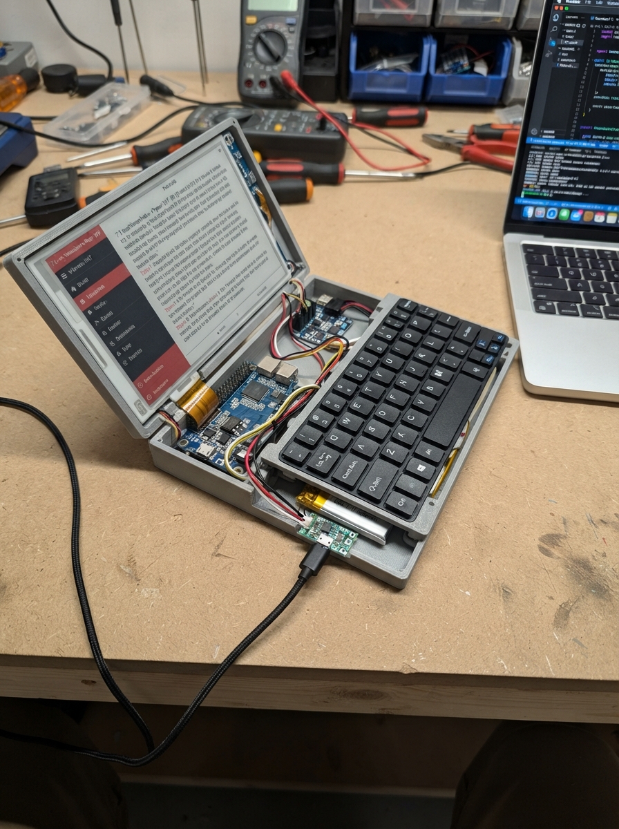
This foldable e-ink reader keyboard combines two 7.5-inch e-Paper displays with a compact PS/2 keyboard in a 3D-printed enclosure, creating a portable dual-screen writing and reading device powered by an ESP32. The red/black/white e-paper screens provide crisp text display with minimal power draw, while the full-width keyboard enables comfortable text input on the go.
This guide provides a complete parts list, wiring diagram showing the dual-display SPI configuration and logic level conversion, step-by-step assembly instructions for the folding case, and Arduino firmware that manages both screens and keyboard input. Builders will learn how to coordinate multiple e-paper displays, handle PS/2 keyboard events, and optimize battery life with a LiPo charging system.
Wiring diagram
Gather all the parts
Assemble it in 6 steps
1. Print a taller folding case
Print foldable_case in black PETG or ABS as two screen panels joined by a wide hinge. Keep the outer panel for outer_epaper. On the inside panel, make the screen pocket at the top and a 222 mm × 120 mm recessed keyboard pocket directly below it for foldout_keyboard. The open device becomes roughly 220 mm wide and 270 mm tall, like a compact laptop rather than a pocket Kindle.
- Measure the purchased keyboard before printing and add 1 mm of side clearance.
- Use a 12–15 mm deep lower case section so the keyboard and its wiring have room.
- Do not clamp, drill through, or press on the e-paper glass — it can crack or keep permanent marks.
- Use a broad hinge wire channel with smooth edges; sharp edges can cut wires each time the case folds.
2. Mount the two e-paper screens
Fit outer_epaper into the outside cover so it is visible while shut. Fit inner_epaper into the upper part of the inside panel, above the keyboard pocket. Hold each board by its edges with M2 standoffs, clips, or thin foam tape; do not put screws or tape on the display surface.
- Route the outer-screen wire bundle through the hinge before closing its rear cover.
- Leave a loose flexible-wire loop in the hinge so opening the case does not pull the wires tight.
- Do not sharply bend a display ribbon or hinge wire; a damaged connection can stop the screen from working.
3. Wire the shared screen lines
For both outer_epaper and inner_epaper, connect VCC → 3V3 (power), GND → GND (ground), DIN → GPIO11 (screen data), and CLK → GPIO12 (screen clock). Connect outer_epaper CS → GPIO10 (outer-screen select), DC → GPIO1 (screen control), RST → GPIO17 (reset), and BUSY → GPIO2 (ready signal). Connect inner_epaper CS → GPIO14 (inner-screen select), DC → GPIO3 (screen control), RST → GPIO18 (reset), and BUSY → GPIO4 (ready signal).
- The shared GPIO11 and GPIO12 wires are intentional; each screen has its own select wire.
- Keep data and clock wires short except for the flexible section passing through the hinge.
- Both e-paper boards use 3.3 V in this design. Connecting either display VCC to 5 V can damage it.
- Make sure VCC and GND are not swapped before connecting either screen.
4. Install the full-width keyboard
Screw or clip foldout_keyboard into its recessed lower pocket with the keys facing up when the reader is open. Connect VCC → keyboard_boost VOUT+ (5 V power), GND → GND (ground), DATA → keyboard_level_shifter HV1 (keyboard signal), and CLK → keyboard_level_shifter HV2 (keyboard clock). Connect keyboard_level_shifter LV → 3V3 (power), HV → keyboard_boost VOUT+ (5 V power), GND → GND (ground), LV1 → GPIO8 (keyboard data), and LV2 → GPIO9 (keyboard clock).
- Put the level shifter close to the keyboard cable, inside the lower electronics cavity.
- Use a removable keyboard bezel or small screws so the keyboard can be serviced later.
- Do not connect the keyboard's 5 V DATA or CLK wire directly to GPIO8 or GPIO9 — 5 V can damage the ESP32.
- The keyboard is permanently mounted but needs a little clearance around the keycaps so the case edge does not hold a key down.
5. Install battery charging and power boards
Secure lipo_battery in the thicker inner-panel cavity with foam tape and a non-metal strap. Connect lipo_battery +V → charger B+ (battery positive) and GND → charger B- (battery ground). Connect charger OUT+ → power_regulator VIN (battery power), charger OUT- → GND (ground), power_regulator GND → GND (ground), and power_regulator VOUT → 3V3 (reader power). Connect keyboard_boost VIN+ → 3V3 (power), VIN- → GND (ground), and VOUT- → GND (ground). Connect charger IN+ → the USB charge input positive wire (charging power) and IN- → its ground wire (ground).
- Place the charge socket on a bottom edge so the reader can charge while closed.
- With the battery disconnected, measure the regulator at 3.3 V and the keyboard boost board at 5.0 V.
- Never puncture, crush, or short the LiPo battery — it can overheat or catch fire.
- Do not connect the ESP32, screens, or keyboard until both power outputs measure correctly.
6. Close the case and test it
Place the ESP32, charger, power boards, and keyboard level shifter in the covered electronics bay with insulating tape beneath exposed solder joints. Confirm no wire is trapped by the main hinge, then fit the covers. The outside screen shows the reader page; open the case and type on the laptop-style keyboard to write notes on the inner screen.
- Tri-color e-paper changes slowly and keeps its picture without continuous power; both are normal.
- Open and close the reader gently at first while checking that the hinge wires stay loose.
- Make sure 3V3 and GND are not swapped anywhere — swapped power can damage the board, screens, or keyboard.
Review all connections
1. Connections between "outer_epaper" and "ESP32"
2. Connections between "inner_epaper" and "ESP32"
3. Connections between "lipo_battery" and "ESP32"
4. Connections between "charger" and "ESP32"
5. Connections between "power_regulator" and "ESP32"
6. Connections between "keyboard_level_shifter" and "ESP32"
7. Connections between "keyboard_boost" and "ESP32"
8. Connections between "foldout_keyboard" and "ESP32"
Deploy the firmware
#include <Arduino.h>
#include <SPI.h>
#include <PS2Keyboard.h>
#include <GxEPD2_3C.h>
#include <epd3c/GxEPD2_750c_Z08.h>

constexpr uint8_t EINK_MOSI = 11;
constexpr uint8_t EINK_SCK = 12;
constexpr uint8_t OUTER_CS = 10;
constexpr uint8_t OUTER_DC = 1;
constexpr uint8_t OUTER_RST = 17;
constexpr uint8_t OUTER_BUSY = 2;
constexpr uint8_t INNER_CS = 14;
constexpr uint8_t INNER_DC = 3;
constexpr uint8_t INNER_RST = 18;
constexpr uint8_t INNER_BUSY = 4;
constexpr uint8_t KEYBOARD_DATA = 8;
constexpr uint8_t KEYBOARD_CLOCK = 9;
constexpr unsigned long NOTE_REDRAW_DELAY_MS = 1500;

using EpdDriver = GxEPD2_750c_Z08;
using EpdDisplay = GxEPD2_3C<EpdDriver, EpdDriver::HEIGHT / 8>;

EpdDisplay outerDisplay(EpdDriver(OUTER_CS, OUTER_DC, OUTER_RST, OUTER_BUSY));
EpdDisplay innerDisplay(EpdDriver(INNER_CS, INNER_DC, INNER_RST, INNER_BUSY));
PS2Keyboard keyboard;

String noteText;
bool noteNeedsRedraw = false;
unsigned long lastKeyAt = 0;

void drawPage(EpdDisplay& display, const String& text)
{
  display.setFullWindow();
  display.firstPage();
  do
  {
    display.fillScreen(GxEPD_WHITE);
    display.setTextColor(GxEPD_BLACK);
    display.setFont(nullptr);

    int16_t y = 28;
    int start = 0;
    while (start <= text.length() && y < display.height() - 18)
    {
      int end = text.indexOf('\n', start);
      if (end < 0) end = text.length();
      display.setCursor(18, y);
      display.print(text.substring(start, end));
      y += 18;
      start = end + 1;
    }
  }
  while (display.nextPage());
}

void showOuterPage()
{
  drawPage(outerDisplay,
           "FOLDABLE E-READER\n\n"
           "Reader screen\n\n"
           "Open the case to use\n"
           "the built-in keyboard\n"
           "and write notes.");
}

void showInnerNote()
{
  String page = "NOTES\n\n";
  page += noteText.length() ? noteText : "Start typing on the\nbuilt-in keyboard.";
  page += "\n\nWait briefly after typing\nto update this screen.";
  drawPage(innerDisplay, page);
}

bool readKeyboard(char& key)
{
  if (!keyboard.available()) return false;
  key = static_cast<char>(keyboard.read());
  return key != 0;
}

void setup()
{
  keyboard.begin(KEYBOARD_DATA, KEYBOARD_CLOCK);
  SPI.begin(EINK_SCK, -1, EINK_MOSI, OUTER_CS);
  outerDisplay.init(115200, true, 2, false);
  innerDisplay.init(115200, true, 2, false);
  showOuterPage();
  showInnerNote();
}

void loop()
{
  char key;
  if (readKeyboard(key))
  {
    if (key == '\b' || key == 0x7F)
    {
      if (noteText.length())
      {
        noteText = noteText.substring(0, noteText.length() - 1);
        noteNeedsRedraw = true;
      }
    }
    else if (key == '\r' || key == '\n')
    {
      if (noteText.length() < 1100)
      {
        noteText += '\n';
        noteNeedsRedraw = true;
      }
    }
    else if (key >= 32 && key <= 126 && noteText.length() < 1100)
    {
      noteText += key;
      noteNeedsRedraw = true;
    }

    if (noteNeedsRedraw) lastKeyAt = millis();
  }

  if (noteNeedsRedraw && millis() - lastKeyAt >= NOTE_REDRAW_DELAY_MS)
  {
    showInnerNote();
    noteNeedsRedraw = false;
  }

  delay(25);
}
Remix this project
Make it yours in one click
Open a full copy of this project in your own Schematik workspace, diagram, code, parts, and assembly steps included. Swap the sensor, add features, or redesign the whole thing with AI. The author's original stays untouched.