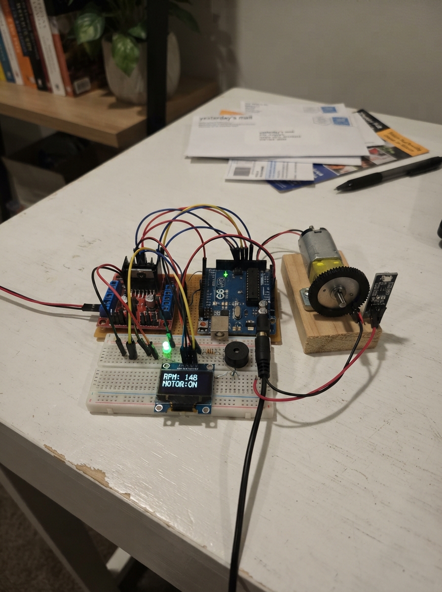
This project builds a closed-loop motor speed controller that reads real-time RPM from an optical encoder and adjusts power delivery to maintain a target speed. The system uses an ESP32 to process sensor pulses, drive an L298N motor module, and display live RPM and control status on an SSD1306 OLED screen, with audio and visual feedback from a buzzer and LED.
The guide provides a complete wiring diagram, parts list, and step-by-step assembly instructions for mounting the optical encoder disc, connecting the motor driver and 12 V power, integrating the speed sensor, and programming the ESP32 with PI control firmware. Builders will learn how to implement motor feedback control, tune PID parameters, and safely commission the system.
Wiring diagram
Gather all the parts
Assemble it in 8 steps
1. Fit the optical encoder disc
Disconnect the 12 V motor supply. Remove the old shaft magnet; the LM393 optical sensor does not use it. Secure encoder_flag concentrically to the motor output shaft. Put its single opening, slot, or thin tab through the gap in speed_sensor so it blocks and clears the invisible infrared beam once per complete motor-shaft turn.
- Turn the shaft slowly by hand and watch that the disc or tab never rubs either side of the sensor slot.
- A one-slot disc gives the firmware one pulse per motor-shaft revolution.
- Disconnect motor power before fitting or adjusting the disc. A loose or unbalanced disc can strike the sensor or fly off when the motor spins.
2. Connect the motor driver and motor
Connect motor_driver OUT1 to motor M+ (motor power) and motor_driver OUT2 to motor M− (motor power). Remove the ENA jumper before using GPIO25 for speed control. Leave the L298N 5V terminal unconnected.
- If the motor turns the wrong way, disconnect the 12 V supply and swap the two motor wires at OUT1 and OUT2.
- Never connect an ESP32 GPIO pin to OUT1 or OUT2; they carry switched motor voltage. The L298N can become hot with high-current motors.
3. Connect the 12 V motor power
Connect supply_12v +12V to motor_driver VS/+12V (motor power) and supply_12v GND to motor_driver GND (ground). Keep these 12 V wires away from the ESP32 3V3 connection.
- Use a supply rated for the motor's startup current, not only its normal running current.
- Do not connect 12 V directly to the ESP32; connecting it to the 3V3 pin will damage the board.
4. Connect the ESP32 motor-control wires
With power disconnected, connect ESP32 GPIO25 to motor_driver ENA (speed-control signal), GPIO26 to motor_driver IN1 (direction signal), GPIO33 to motor_driver IN2 (direction signal), and ESP32 GND to motor_driver GND (shared ground).
- The shared ground gives the ESP32 control signals the same reference as the motor driver.
- Make sure the ENA jumper is removed before connecting GPIO25, otherwise the motor channel may stay permanently enabled.
5. Wire the LM393 optical speed sensor
Use the labels printed on speed_sensor: connect VCC to ESP32 3V3 (power), GND to ESP32 GND (ground), and DO or D0 to ESP32 GPIO27 (RPM signal). Supply it from 3.3 V, not 5 V, so its digital output is safe for the ESP32 input.
- Slowly turn the shaft by hand and adjust the module’s small screw until its indicator changes state once as the encoder opening or tab passes through the slot.
- Do not place the disc against the sensor; it must pass freely through the slot. Do not use 5 V power with DO connected directly to GPIO27 because that can damage the ESP32.
6. Add the restart button
Use the two terminals of restart_button. Connect one terminal marked SIGNAL to ESP32 GPIO13 (restart signal) and the other terminal marked GND to ESP32 GND (ground). When the display says STOPPED, press this button once to start the motor again.
- This wiring uses the ESP32’s built-in pull-up, so you do not need an extra resistor.
- If a four-leg tactile button is used, use one leg from each opposite side; the two legs on the same side are already connected together.
- Keep this button wiring away from the L298N OUT1 and OUT2 terminals because those terminals carry motor voltage.
7. Wire the display and indicators
Connect oled VCC to ESP32 3V3 (power), oled GND to ESP32 GND (ground), oled SDA to GPIO21 (data), and oled SCL to GPIO22 (clock). Connect GPIO32 to led_resistor P1 (signal), led_resistor P2 to status_led ANODE (current limiting), and status_led GND to ESP32 GND (ground). Connect buzzer SIGNAL to GPIO4 (sound signal) and buzzer GND to ESP32 GND (ground).
- The LED's longer leg is normally the positive leg and goes toward the resistor; its shorter leg goes to GND.
- Make sure OLED VCC and GND are not swapped — swapped power can damage the display. Do not omit the 220 Ω LED resistor.
8. Power and test in a safe order
Check every wire against the diagram, keep fingers, clothing, and loose wires away from the shaft, then power the ESP32 over USB. Finally connect the 12 V supply to the L298N. If the motor stops because no speed pulses arrive for about two seconds, the buzzer sounds and the display says STOPPED; correct any mechanical jam, then press restart_button once.
- If RPM stays at zero, first check that the encoder disc actually blocks the sensor beam and then adjust the small sensor screw.
- Disconnect the 12 V supply before changing motor, disc, sensor, or button wiring.
Review all connections
1. Connections between "supply_12v" and "ESP32"
2. Connections between "motor_driver" and "ESP32"
3. Connections between "oled" and "ESP32"
4. Connections between "status_led" and "ESP32"
5. Connections between "led_resistor" and "ESP32"
6. Connections between "buzzer" and "ESP32"
7. Connections between "speed_sensor" and "ESP32"
8. Connections between "restart_button" and "ESP32"
Deploy the firmware
#include <Arduino.h>
#include <Wire.h>
#include <Adafruit_GFX.h>
#include <Adafruit_SSD1306.h>

constexpr uint8_t MOTOR_ENA_PIN = 25;
constexpr uint8_t MOTOR_IN1_PIN = 26;
constexpr uint8_t MOTOR_IN2_PIN = 33;
constexpr uint8_t SPEED_SENSOR_PIN = 27;
constexpr uint8_t OLED_SDA_PIN = 21;
constexpr uint8_t OLED_SCL_PIN = 22;
constexpr uint8_t STATUS_LED_PIN = 32;
constexpr uint8_t BUZZER_PIN = 4;
constexpr uint8_t RESTART_BUTTON_PIN = 13;

constexpr uint8_t OLED_WIDTH = 128;
constexpr uint8_t OLED_HEIGHT = 64;
constexpr uint8_t OLED_ADDRESS = 0x3C;
constexpr uint16_t PWM_FREQUENCY = 20000;
constexpr uint8_t PWM_RESOLUTION = 8;
constexpr uint8_t PWM_MAX = 255;
constexpr uint16_t PULSES_PER_REVOLUTION = 1; // One optical encoder slot or flag per revolution.
// Desired shaft speed. Change this only after verifying the real RPM with the OLED.
constexpr float TARGET_RPM = 120.0F;
constexpr uint32_t SAMPLE_INTERVAL_MS = 200;
// Conservative PI gains: the output is also limited to small steps to prevent hunting.
constexpr float KP = 0.10F;
constexpr float KI = 0.03F;
constexpr uint8_t RESTART_PWM_DUTY = 180;
constexpr uint32_t STARTUP_GRACE_MS = 3000;
constexpr uint32_t SENSOR_TIMEOUT_MS = 2000;
constexpr uint32_t BUTTON_DEBOUNCE_MS = 50;

Adafruit_SSD1306 display(OLED_WIDTH, OLED_HEIGHT, &Wire, -1);
volatile uint32_t hallPulses = 0;
volatile uint32_t lastPulseUs = 0;
volatile uint32_t pulsePeriodUs = 0;
volatile uint32_t pulseSequence = 0;
uint32_t lastSampleMs = 0;
uint32_t lastDisplayMs = 0;
uint32_t motorStartMs = 0;
uint32_t lastControlledPulseSequence = 0;
float measuredRpm = 0.0F;
float integralError = 0.0F;
uint8_t pwmDuty = RESTART_PWM_DUTY;
bool displayReady = false;
bool motorStopped = false;
bool lastButtonReading = HIGH;
uint32_t lastButtonPressMs = 0;

void IRAM_ATTR onSpeedPulse() {
  const uint32_t nowUs = micros();
  if (lastPulseUs != 0) {
    pulsePeriodUs = nowUs - lastPulseUs;
  }
  lastPulseUs = nowUs;
  hallPulses++;
  pulseSequence++;
}

void drawDisplay() {
  if (!displayReady) return;

  display.clearDisplay();
  display.setTextColor(SSD1306_WHITE);
  display.setTextSize(1);
  display.setCursor(0, 0);
  display.print("DC MOTOR CONTROL");
  display.setCursor(0, 16);
  display.print("RPM: ");
  display.print(measuredRpm, 0);
  display.setCursor(0, 28);
  display.print("SET: ");
  display.print(TARGET_RPM, 0);
  display.setCursor(0, 40);
  display.print("PWM: ");
  display.print((100UL * pwmDuty) / PWM_MAX);
  display.print('%');
  display.setCursor(0, 54);
  if (motorStopped) {
    display.print("STOPPED: PRESS BUTTON");
  } else {
    display.print("Optical: GPIO27  1 pulse/rev");
  }
  display.display();
}

void setup() {
  pinMode(MOTOR_IN1_PIN, OUTPUT);
  pinMode(MOTOR_IN2_PIN, OUTPUT);
  pinMode(STATUS_LED_PIN, OUTPUT);
  pinMode(BUZZER_PIN, OUTPUT);
  pinMode(SPEED_SENSOR_PIN, INPUT_PULLUP);
  pinMode(RESTART_BUTTON_PIN, INPUT_PULLUP);

  // Forward direction. Swap the two motor wires at OUT1/OUT2 to reverse it.
  digitalWrite(MOTOR_IN1_PIN, HIGH);
  digitalWrite(MOTOR_IN2_PIN, LOW);
  digitalWrite(STATUS_LED_PIN, LOW);
  digitalWrite(BUZZER_PIN, LOW);

  ledcAttach(MOTOR_ENA_PIN, PWM_FREQUENCY, PWM_RESOLUTION);
  // Start automatically; the controller changes this value as it measures speed.
  ledcWrite(MOTOR_ENA_PIN, pwmDuty);

  Wire.begin(OLED_SDA_PIN, OLED_SCL_PIN);
  displayReady = display.begin(SSD1306_SWITCHCAPVCC, OLED_ADDRESS);
  if (displayReady) {
    drawDisplay();
  }

  // The LM393 optical module produces an active-low pulse when its light beam is interrupted.
  attachInterrupt(digitalPinToInterrupt(SPEED_SENSOR_PIN), onSpeedPulse, FALLING);
  lastSampleMs = millis();
  motorStartMs = lastSampleMs;
}

void loop() {
  const uint32_t now = millis();
  const bool buttonReading = digitalRead(RESTART_BUTTON_PIN);
  if (buttonReading == LOW && lastButtonReading == HIGH &&
      now - lastButtonPressMs >= BUTTON_DEBOUNCE_MS) {
    // A press after a stop gives the motor a fresh starting drive.
    motorStopped = false;
    integralError = 0.0F;
    pwmDuty = RESTART_PWM_DUTY;
    motorStartMs = now;
    lastControlledPulseSequence = 0;
    ledcWrite(MOTOR_ENA_PIN, pwmDuty);
    digitalWrite(BUZZER_PIN, LOW);
    lastButtonPressMs = now;
  }
  lastButtonReading = buttonReading;

  if (now - lastSampleMs >= SAMPLE_INTERVAL_MS) {
    noInterrupts();
    const uint32_t latestPulseUs = lastPulseUs;
    const uint32_t latestPeriodUs = pulsePeriodUs;
    const uint32_t latestSequence = pulseSequence;
    interrupts();

    const uint32_t elapsedMs = now - lastSampleMs;
    const float elapsedSeconds = elapsedMs / 1000.0F;
    lastSampleMs = now;
    const uint32_t pulseAgeUs = micros() - latestPulseUs;
    const bool recentPulse = latestPulseUs != 0 && pulseAgeUs < SENSOR_TIMEOUT_MS * 1000UL;

    // With one flag per revolution, pulse spacing gives a stable RPM value even
    // though a new pulse arrives only about twice per second at 120 RPM.
    if (recentPulse && latestPeriodUs > 0) {
      measuredRpm = 60000000.0F / (PULSES_PER_REVOLUTION * latestPeriodUs);
    } else if (!recentPulse) {
      measuredRpm = 0.0F;
    }

    // Change drive only after a new encoder pulse. With one flag per shaft turn,
    // this avoids reacting repeatedly to the same RPM reading.
    if (!motorStopped && latestSequence != lastControlledPulseSequence && latestPeriodUs > 0) {
      const float error = TARGET_RPM - measuredRpm;
      integralError = constrain(integralError + error * elapsedSeconds, -200.0F, 200.0F);
      const float requestedChange = (KP * error) + (KI * integralError);
      // Limit one correction so a noisy pulse cannot cause a large speed swing.
      const int pwmChange = constrain(static_cast<int>(requestedChange), -12, 12);
      pwmDuty = static_cast<uint8_t>(constrain(static_cast<int>(pwmDuty) + pwmChange, 0, PWM_MAX));
      ledcWrite(MOTOR_ENA_PIN, pwmDuty);
      lastControlledPulseSequence = latestSequence;
    }

    // Stop only for a real loss of sensor movement, not for a small RPM error.
    if (!motorStopped && now - motorStartMs >= STARTUP_GRACE_MS && !recentPulse) {
      motorStopped = true;
      pwmDuty = 0;
      ledcWrite(MOTOR_ENA_PIN, 0);
    }

    digitalWrite(STATUS_LED_PIN, recentPulse ? HIGH : LOW);
    // Buzz only while the controller is waiting for the restart button.
    digitalWrite(BUZZER_PIN, motorStopped ? HIGH : LOW);
  }

  if (now - lastDisplayMs >= SAMPLE_INTERVAL_MS) {
    drawDisplay();
    lastDisplayMs = now;
  }
}
Remix this project
Make it yours in one click
Open a full copy of this project in your own Schematik workspace, diagram, code, parts, and assembly steps included. Swap the sensor, add features, or redesign the whole thing with AI. The author's original stays untouched.