Community project
Four-Channel Inverted BCD
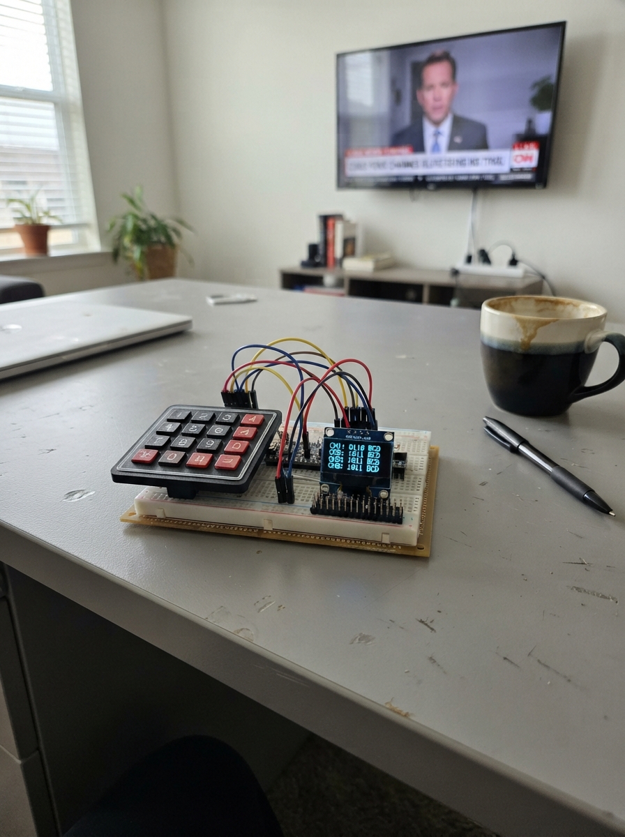
This project builds a four-channel inverted BCD (Binary Coded Decimal) output controller using an Arduino Uno. The 4×4 matrix keypad lets you enter decimal values (0–9) for each of the four channels, which are then encoded as inverted BCD signals on the 2×8 pin header. The SSD1306 OLED display shows your current entry and applied values in real time.
The guide includes a complete wiring diagram, parts list, and Arduino firmware that handles keypad input, BCD encoding, and display updates. Follow the assembly steps to connect the OLED screen and keypad ribbon, wire the four inverted-BCD output pins, then use the keypad to enter and apply your values to each channel.
Wiring diagram

Gather all the parts
Assemble it in 4 steps
1. Connect the OLED screen
Connect the OLED VCC pin to the Mega 5V pin (power), OLED GND to Mega GND (ground), OLED SDA to Mega D20 (data), and OLED SCL to Mega D21 (clock).
- Make sure VCC and GND are not swapped — swapped power can damage the screen.
2. Connect the keypad ribbon
Connect the 4×4 keypad pins in the order printed on its ribbon: R1 → Mega D30 (signal), R2 → D31 (signal), R3 → D44 (signal), R4 → D45 (signal), C1 → D46 (signal), C2 → D26 (signal), C3 → D27 (signal), and C4 → D28 (signal).
- The keypad needs no VCC or GND wire; its eight ribbon wires go directly to the Mega pins.
3. Wire the four inverted-BCD outputs
Use the 16-pin header for external BCD equipment: channel 1 has D22=8, D23=4, D24=2, D25=1; channel 2 has D29=8, D6=4, D7=2, D8=1; channel 3 has D9=8, D10=4, D11=2, D12=1; channel 4 has D13=8, D14=4, D15=2, D16=1. Each pin is an inverted output: LOW represents a BCD bit of 1, and HIGH represents a BCD bit of 0.
- Only connect these 5 V logic outputs to equipment that accepts 5 V logic. Use a level converter if the other equipment requires 3.3 V.
4. Enter and apply the four values
After deploying, press four number keys in order: the first is channel 1, then channel 2, channel 3, and channel 4. Press # to copy the values to the four inverted-BCD output groups. Press * to erase the entered values before applying them.
- The OLED shows each entered digit and the four final inverted BCD bits for every channel.
Review all connections
1. Connections between "keypad_4x4" and "Arduino"
2. Connections between "oled_1" and "Arduino"
3. Connections between "bcd_output_header" and "Arduino"
Deploy the firmware
#include <Arduino.h>
#include <Wire.h>
#include <Keypad.h>
#include <Adafruit_GFX.h>
#include <Adafruit_SSD1306.h>

const uint8_t CH1_8_PIN = 22;
const uint8_t CH1_4_PIN = 23;
const uint8_t CH1_2_PIN = 24;
const uint8_t CH1_1_PIN = 25;
const uint8_t CH2_8_PIN = 29;
const uint8_t CH2_4_PIN = 6;
const uint8_t CH2_2_PIN = 7;
const uint8_t CH2_1_PIN = 8;
const uint8_t CH3_8_PIN = 9;
const uint8_t CH3_4_PIN = 10;
const uint8_t CH3_2_PIN = 11;
const uint8_t CH3_1_PIN = 12;
const uint8_t CH4_8_PIN = 13;
const uint8_t CH4_4_PIN = 14;
const uint8_t CH4_2_PIN = 15;
const uint8_t CH4_1_PIN = 16;

const uint8_t bcdPins[4][4] = {
  {CH1_8_PIN, CH1_4_PIN, CH1_2_PIN, CH1_1_PIN},
  {CH2_8_PIN, CH2_4_PIN, CH2_2_PIN, CH2_1_PIN},
  {CH3_8_PIN, CH3_4_PIN, CH3_2_PIN, CH3_1_PIN},
  {CH4_8_PIN, CH4_4_PIN, CH4_2_PIN, CH4_1_PIN}
};

const byte ROWS = 4;
const byte COLS = 4;
char keys[ROWS][COLS] = {
  {'1', '2', '3', 'A'}, {'4', '5', '6', 'B'},
  {'7', '8', '9', 'C'}, {'*', '0', '#', 'D'}
};
byte rowPins[ROWS] = {30, 31, 44, 45};
byte colPins[COLS] = {46, 26, 27, 28};
Keypad keypad = Keypad(makeKeymap(keys), rowPins, colPins, ROWS, COLS);

Adafruit_SSD1306 display(128, 64, &Wire, -1);
uint8_t enteredValues[4] = {0, 0, 0, 0};
uint8_t outputValues[4] = {0, 0, 0, 0};
uint8_t entryPosition = 0;

void writeInvertedBcd(uint8_t channel, uint8_t value) {
  for (uint8_t bit = 0; bit < 4; bit++) {
    uint8_t mask = static_cast<uint8_t>(8 >> bit);
    digitalWrite(bcdPins[channel][bit], (value & mask) ? LOW : HIGH);
  }
}

void applyOutputs() {
  for (uint8_t channel = 0; channel < 4; channel++) {
    outputValues[channel] = enteredValues[channel];
    writeInvertedBcd(channel, outputValues[channel]);
  }
}

void printInvertedBits(uint8_t value) {
  for (int8_t bit = 3; bit >= 0; bit--) {
    display.print((value & (1 << bit)) ? '0' : '1');
  }
}

void drawScreen() {
  display.clearDisplay();
  display.setTextColor(SSD1306_WHITE);
  display.setTextSize(1);
  display.setCursor(0, 0);
  display.println(F("4CH INVERTED BCD"));
  display.println(F("Enter 4 digits: 0-9"));
  for (uint8_t channel = 0; channel < 4; channel++) {
    display.print(F("CH"));
    display.print(channel + 1);
    display.print(F(":"));
    display.print(enteredValues[channel]);
    display.print(channel == entryPosition && entryPosition < 4 ? F(" < ") : F("   "));
    display.print(F("OUT:"));
    printInvertedBits(outputValues[channel]);
    display.println();
  }
  display.println(F("#=RUN  *=CLEAR"));
  display.display();
}

void clearEntry() {
  for (uint8_t channel = 0; channel < 4; channel++) enteredValues[channel] = 0;
  entryPosition = 0;
}

void setup() {
  for (uint8_t channel = 0; channel < 4; channel++) {
    for (uint8_t bit = 0; bit < 4; bit++) pinMode(bcdPins[channel][bit], OUTPUT);
    writeInvertedBcd(channel, 0);
  }
  if (!display.begin(SSD1306_SWITCHCAPVCC, 0x3C)) for (;;) { }
  drawScreen();
}

void loop() {
  char key = keypad.getKey();
  if (key == NO_KEY) return;
  if (key >= '0' && key <= '9' && entryPosition < 4) {
    enteredValues[entryPosition++] = static_cast<uint8_t>(key - '0');
    drawScreen();
  } else if (key == '*') {
    clearEntry();
    drawScreen();
  } else if (key == '#') {
    applyOutputs();
    entryPosition = 0;
    drawScreen();
  }
}
Remix this project
Make it yours in one click
Open a full copy of this project in your own Schematik workspace — diagram, code, parts, and assembly steps included. Swap the sensor, add features, or redesign the whole thing with AI. The author's original stays untouched.