Community project
Garage Approach Alert
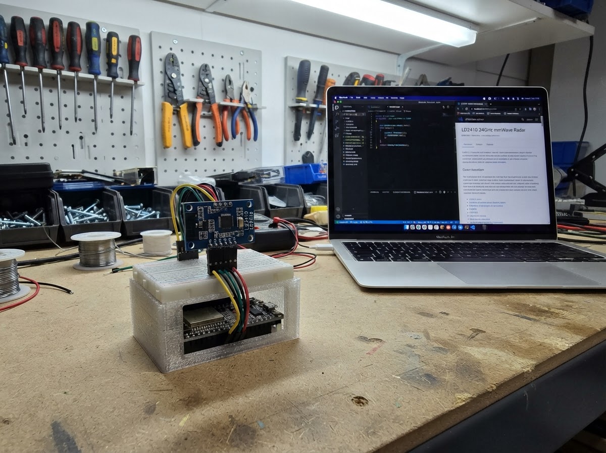
The Garage Approach Alert uses two LD2410 24GHz millimeter-wave radar sensors to detect motion in a garage entryway from two different distances. One sensor monitors the far zone toward the house, while the other watches the near zone at the garage door, providing early warning of approaching vehicles or people. This guide includes a wiring diagram, complete parts list, ESP32 firmware with a web dashboard, and step-by-step assembly instructions to get the dual-radar station up and running.
The project creates a local WiFi access point that displays real-time presence detection from both radar zones on a mobile-friendly web interface. Builders will learn how to integrate multiple presence sensors with an ESP32, configure independent detection zones, and create a responsive status dashboard—all without requiring cloud connectivity or external services.
Wiring diagram

Gather all the parts
Assemble it in 7 steps
1. Keep the camera board accessible
Place the AI Thinker ESP32-CAM inside the garage where USB power can reach it and where its antenna has a clear path to the phone/computer used for the local status page. The camera itself is not used by this simplified detector, but its fixed camera pins must remain unused.
- Use a stable 5 V USB supply; two LD2410 modules can draw substantial current at startup.
- Do not enclose the ESP32-CAM antenna in metal.
2. Mount the far radar
Mount radar_far at the house-side portion of the normal walking route, aimed across the route rather than straight down it. Keep the front radar area clear of metal, foil insulation, and large wiring bundles.
- Mount in a dry location or non-metallic plastic enclosure.
- Begin with a narrow, controlled sensing zone to reduce false triggers.
- The LD2410 detects presence, not a person's identity.
3. Mount the near radar
Mount radar_near near the garage-side end of the route, aimed across the final approach. Keep its detection field away from the road, moving garage equipment, and trees if possible.
- Separate the two sensor fields as much as practical so they represent distinct zones.
4. Make the shared power connections
Connect both radar VCC pins to the ESP32-CAM 5 V/VIN rail and connect both radar GND pins to ESP32-CAM GND. All three devices must share the same ground.
- Use short, secure power wiring and a USB supply with comfortable current margin.
- Do not power either radar from the ESP32-CAM 3.3 V pin; the LD2410 requires 5 V.
5. Wire the two status outputs
Connect radar_far OUT directly to ESP32-CAM GPIO16. Connect radar_near OUT directly to ESP32-CAM GPIO17. The LD2410 OUT output is 3.3 V logic, so no divider or level shifter is used.
- Check the silkscreen labels carefully: use OUT, not TX.
- Keep these signal wires away from the radar antenna face where possible.
- Do not apply 5 V to GPIO16 or GPIO17.
- Leave the radar TX and RX pins insulated and unconnected in this build.
6. Inspect before powering
Verify that each radar has VCC to 5 V, GND to GND, far OUT to GPIO16, and near OUT to GPIO17. Confirm there are no connections to the ESP32-CAM camera pins or to GPIO0.
- A paper label on each sensor—FAR and NEAR—helps avoid swapping zones later.
- GPIO0 is used for boot/programming and must not be tied to a radar signal.
7. Power the completed station
Connect the ESP32-CAM to its USB power source only after completing the inspection. The board, both radars, and their shared ground will power together.
- After deployment, connect a phone or computer to the Garage-Approach Wi-Fi network and open 192.168.4.1 to view the two zones.
Review all connections
1. Connections between "radar_far" and "ESP32"
2. Connections between "radar_near" and "ESP32"
Deploy the firmware
#include <Arduino.h>
#include <WiFi.h>
#include <WebServer.h>


// Forward declarations
String statusMessage();
void handleStatus();

constexpr int RADAR_FAR_PIN = 16;
constexpr int RADAR_NEAR_PIN = 17;
constexpr unsigned long HOLD_MS = 5000;

const char *AP_SSID = "Garage-Approach";
const char *AP_PASSWORD = "garagealert";

WebServer server(80);
bool farActive = false;
bool nearActive = false;
unsigned long farLastSeen = 0;
unsigned long nearLastSeen = 0;

const char PAGE[] PROGMEM = R"HTML(
<!doctype html><html><head><meta name="viewport" content="width=device-width,initial-scale=1">
<title>Garage Approach</title><style>
body{margin:0;background:#10151b;color:#eef3f8;font-family:Arial,sans-serif;text-align:center}main{max-width:520px;margin:auto;padding:26px 18px}h1{font-size:1.7rem;margin:.2em}p,small{color:#aab8c5}#state{font-weight:bold;font-size:1.4rem;margin:22px 0;padding:16px;border-radius:12px;background:#1b252f}.zones{display:flex;gap:14px}.zone{flex:1;background:#1b252f;border-radius:14px;padding:22px 8px;font-size:1.05rem}.dot{width:55px;height:55px;border-radius:50%;margin:13px auto;background:#34414c}.on{background:#ff3939;box-shadow:0 0 25px #ff2020}small{display:block;margin-top:26px}</style></head><body><main>
<h1>Garage Approach Radar</h1><p>LD2410 two-zone presence monitor</p><div id="state">Loading...</div><div class="zones"><div class="zone">FAR / HOUSE SIDE<div id="far" class="dot"></div><span id="farText">-</span></div><div class="zone">NEAR / GARAGE<div id="near" class="dot"></div><span id="nearText">-</span></div></div><small>Updates when a zone state changes.</small></main><script>
let previous='';async function poll(){try{let d=await (await fetch('/status')).json();let key=JSON.stringify(d);if(key!==previous){previous=key;document.getElementById('far').className='dot '+(d.far?'on':'');document.getElementById('near').className='dot '+(d.near?'on':'');document.getElementById('farText').textContent=d.far?'DETECTED':'CLEAR';document.getElementById('nearText').textContent=d.near?'DETECTED':'CLEAR';document.getElementById('state').textContent=d.message;}}catch(e){document.getElementById('state').textContent='Connection lost';}}poll();setInterval(poll,500);</script></body></html>
)HTML";

String statusMessage() {
  if (nearActive) return "PERSON NEAR GARAGE";
  if (farActive) return "APPROACH DETECTED";
  return "ALL CLEAR";
}

void handleStatus() {
  String json = "{\"far\":" + String(farActive ? "true" : "false") + ",\"near\":" + String(nearActive ? "true" : "false") + ",\"message\":\"" + statusMessage() + "\"}";
  server.send(200, "application/json", json);
}

void setup() {
  pinMode(RADAR_FAR_PIN, INPUT);
  pinMode(RADAR_NEAR_PIN, INPUT);
  WiFi.mode(WIFI_AP);
  WiFi.softAP(AP_SSID, AP_PASSWORD);
  server.on("/", HTTP_GET, []() { server.send_P(200, "text/html", PAGE); });
  server.on("/status", HTTP_GET, handleStatus);
  server.onNotFound([]() { server.send(404, "text/plain", "Not found"); });
  server.begin();
}

void loop() {
  const unsigned long now = millis();
  if (digitalRead(RADAR_FAR_PIN) == HIGH) farLastSeen = now;
  if (digitalRead(RADAR_NEAR_PIN) == HIGH) nearLastSeen = now;
  farActive = (now - farLastSeen) < HOLD_MS;
  nearActive = (now - nearLastSeen) < HOLD_MS;
  server.handleClient();
}
Remix this project
Make it yours in one click
Open a full copy of this project in your own Schematik workspace — diagram, code, parts, and assembly steps included. Swap the sensor, add features, or redesign the whole thing with AI. The author's original stays untouched.