Community project
GPS Speed Display
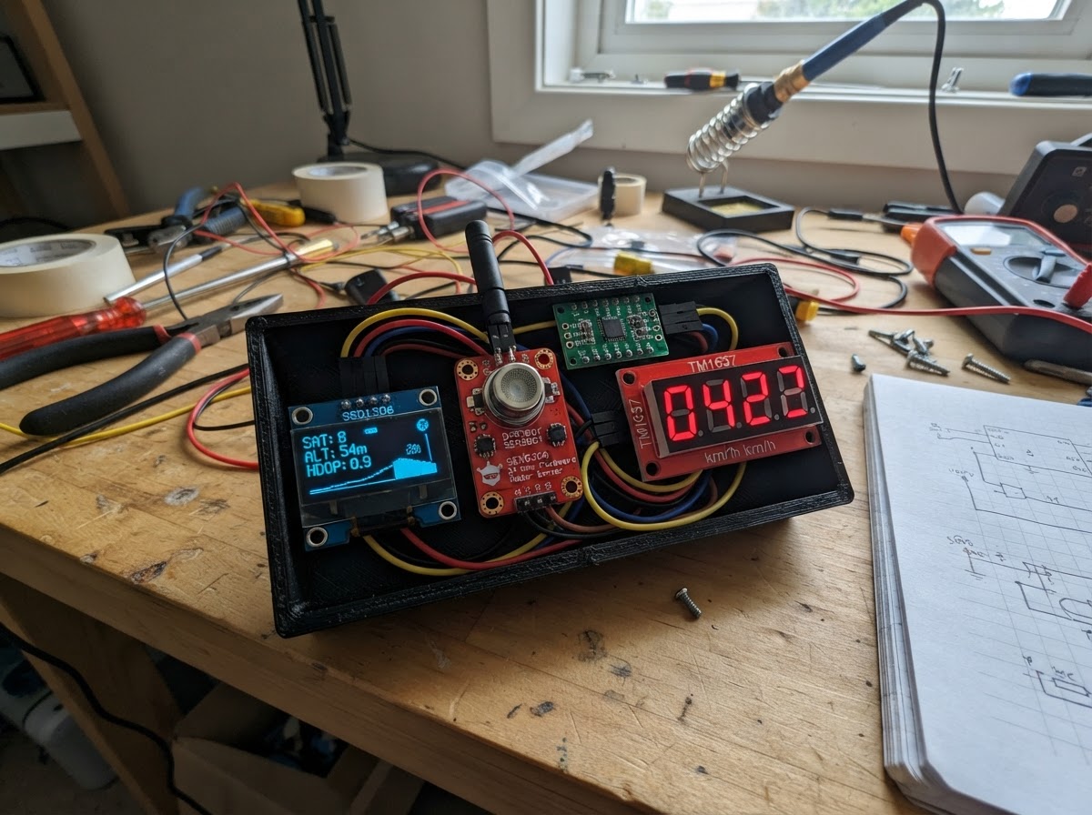
This project builds a roadside speed display that uses a 24 GHz microwave radar sensor to detect vehicle speeds and show them on a large 4-digit 7-segment display visible from the road. The ESP32 microcontroller processes radar data and manages both the bright red speed display for drivers and a smaller OLED status screen for setup and monitoring.
The guide provides a complete parts list, wiring diagram showing all connections including the logic level converter for sensor compatibility, step-by-step assembly instructions, and ready-to-upload firmware. Builders will learn how to integrate radar sensing with dual displays, configure the sensor for accurate speed detection, and safely mount the system for roadside use.
Wiring diagram
Gather all the parts
Assemble it in 6 steps
1. Place the roadside parts safely
Put the ESP32, radar, level-converter board, OLED, and red number display inside a dry non-metal enclosure. Cut a clear opening for the red display. Point the radar face toward one driveway lane, as nearly straight along the cars’ travel direction as practical; it reads the speed toward or away from it best.
- Mount the radar about waist to chest height and keep trees, gates, and parked cars out of its view as much as possible.
- Use the OLED only as a setup/status screen; the large red digits are the driver-facing display.
- Do not use this as an enforcement or safety device: a one-sided radar reading is approximate and can be affected by its angle and by nearby moving objects.
- Keep every electronic part dry. Water on exposed boards can short them and damage the USB-powered ESP32.
2. Connect power and ground
Use red wires: radar VCC → ESP32 5V/VIN (power), level converter HV → ESP32 5V/VIN (power), and red display VCC → ESP32 5V/VIN (power). Use a separate red wire: level converter LV → ESP32 3V3 (power). Use black wires: radar GND, converter GND, red display GND, OLED GND → ESP32 GND (ground). Finally connect OLED VCC → ESP32 3V3 (power).
- A breadboard ground row can join the black wires before one wire goes to ESP32 GND.
- The ESP32 receives USB power; do not connect this circuit directly to a vehicle battery or roadside mains supply.
- Make sure VCC and GND are not swapped — swapped power can damage the radar, displays, or ESP32.
- The 5V and 3V3 pins are different: connect converter HV to 5V/VIN and converter LV to 3V3 exactly as stated.
3. Connect the radar data wire
Connect radar TX → level converter HV1 (radar data). Connect level converter LV1 → ESP32 GPIO16 (safe radar data). Connect radar MODE → ESP32 GND (mode selection). Leave radar RX unconnected.
- Follow the labels printed beside each converter pin: HV is the 5 V side and LV is the ESP32’s 3.3 V side.
- Do not connect the radar’s 5 V TX pin directly to GPIO16 — the higher voltage can damage the ESP32 pin.
4. Connect the large red speed display
Connect level converter LV2 → ESP32 GPIO18 (clock signal), then level converter HV2 → red display CLK (clock signal). Connect level converter LV3 → ESP32 GPIO19 (data signal), then level converter HV3 → red display DIO (data signal).
- These are two separate converter channels: keep channel 2 with CLK and channel 3 with DIO.
- The red display will show four dashes when no vehicle is detected.
- Do not bypass the converter board: a 5 V pull-up inside many red display modules can send too much voltage into ESP32 GPIO18 or GPIO19.
5. Connect the small setup screen
Connect OLED SDA → ESP32 GPIO21 (data), and OLED SCL → ESP32 GPIO22 (clock). The OLED VCC and GND connections were made in step 2.
- Read the tiny labels on the OLED board carefully; SDA and SCL are easy to swap.
- Make sure VCC and GND are not swapped — swapped power can damage the OLED screen.
6. Aim and test the display
Secure all boards so no metal pins can touch, then plug the ESP32 into USB. The OLED should say “RADAR READY” and the red display should show dashes. Walk or slowly drive one vehicle through the selected lane and adjust the radar angle until the reading is steady. The speed remains visible for about three seconds after the target disappears.
- Test with only one moving vehicle and no nearby pedestrians at first, then make small aiming adjustments.
- A radar set at an angle to traffic reads lower than the true vehicle speed, so aim as close to along-the-lane as the one-sided mounting allows.
- Do not stand in the driveway while testing with a moving car. Have the driver proceed slowly and use a clear, controlled private area.
Review all connections
1. Connections between "oled_1" and "ESP32"
2. Connections between "radar_1" and "ESP32"
3. Connections between "level_shifter_1" and "ESP32"
4. Connections between "speed_display_1" and "ESP32"
Deploy the firmware
#include <Arduino.h>
#include <Wire.h>
#include <math.h>
#include <DFRobot_C4002.h>
#include <TM1637Display.h>
#include <Adafruit_GFX.h>
#include <Adafruit_SSD1306.h>


// Forward declarations
void drawStatus(const char *line1, const char *line2);
void showSpeed(int speedKph);
void showWaiting();

constexpr int RADAR_RX_PIN = 16;
constexpr int DISPLAY_CLK_PIN = 18;
constexpr int DISPLAY_DIO_PIN = 19;
constexpr int OLED_SDA_PIN = 21;
constexpr int OLED_SCL_PIN = 22;
constexpr uint8_t OLED_ADDRESS = 0x3C;
constexpr unsigned long HOLD_TIME_MS = 3000;

HardwareSerial radarSerial(2);
DFRobot_C4002_UART radar(&radarSerial);
TM1637Display roadDisplay(DISPLAY_CLK_PIN, DISPLAY_DIO_PIN);
Adafruit_SSD1306 statusDisplay(128, 64, &Wire, -1);

int lastShownKph = -1;
unsigned long lastTargetMs = 0;
bool showingDashes = false;

void drawStatus(const char *line1, const char *line2) {
  statusDisplay.clearDisplay();
  statusDisplay.setTextColor(SSD1306_WHITE);
  statusDisplay.setTextSize(2);
  statusDisplay.setCursor(0, 4);
  statusDisplay.println(line1);
  statusDisplay.setTextSize(1);
  statusDisplay.setCursor(0, 36);
  statusDisplay.println(line2);
  statusDisplay.display();
}

void showSpeed(int speedKph) {
  roadDisplay.showNumberDec(speedKph, false, 4, 0);
  char text[18];
  snprintf(text, sizeof(text), "%d km/h", speedKph);
  drawStatus("ROAD SPEED", text);
  lastShownKph = speedKph;
  showingDashes = false;
}

void showWaiting() {
  const uint8_t dashes[] = {0x40, 0x40, 0x40, 0x40};
  roadDisplay.setSegments(dashes);
  drawStatus("RADAR READY", "Aim at one lane");
  showingDashes = true;
  lastShownKph = -1;
}

void setup() {
  Serial.begin(115200);
  radarSerial.begin(115200, SERIAL_8N1, RADAR_RX_PIN, -1);
  radar.begin();

  roadDisplay.setBrightness(7, true);
  Wire.begin(OLED_SDA_PIN, OLED_SCL_PIN);
  if (!statusDisplay.begin(SSD1306_SWITCHCAPVCC, OLED_ADDRESS)) {
    while (true) delay(1000);
  }
  showWaiting();
}

void loop() {
  radar.getSensorStatus();

  if (radar.getTargetState()) {
    // A positive or negative value denotes direction. This roadside sign shows
    // only the speed magnitude to the driver.
    const int speedKph = abs((int)lroundf(radar.getTargetSpeed()));
    if (speedKph > 0 && speedKph <= 99) {
      lastTargetMs = millis();
      if (speedKph != lastShownKph || showingDashes) showSpeed(speedKph);
    }
  }

  if (!showingDashes && millis() - lastTargetMs >= HOLD_TIME_MS) showWaiting();
  delay(20);
}
Remix this project
Make it yours in one click
Open a full copy of this project in your own Schematik workspace — diagram, code, parts, and assembly steps included. Swap the sensor, add features, or redesign the whole thing with AI. The author's original stays untouched.