Community project
Bluetooth ESP32 Gamepad
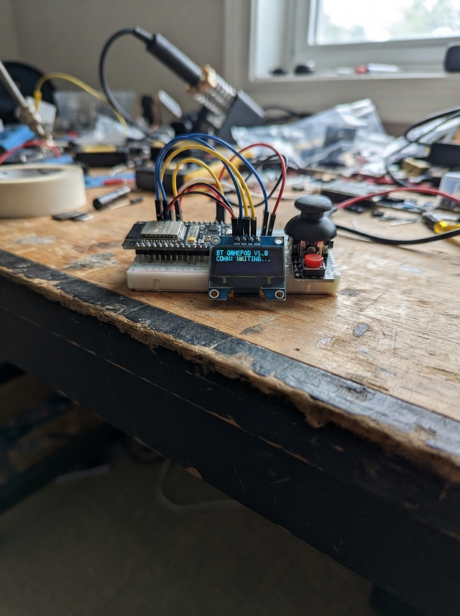
Build a wireless gamepad controller using an ESP32 microcontroller that connects to computers, phones, and gaming devices via Bluetooth. The device features dual analog joysticks for precise movement control, four action buttons for gameplay, and a small OLED display that shows pairing status.
This guide provides a complete parts list, wiring diagram, and step-by-step assembly instructions to connect the joystick modules, buttons, and display to the ESP32. The included firmware implements HID gamepad protocol over Bluetooth, making the controller immediately compatible with most games and applications that support standard gamepads.
Wiring diagram

Gather all the parts
Assemble it in 5 steps
1. Keep power disconnected
Leave the ESP32 unplugged while placing the parts and jumpers. Put the ESP32 DevKit V1, oled_1, joystick_left, joystick_right, button_a, button_b, button_x, and button_y on a breadboard or insulated surface.
- Use breadboard ground and 3.3V rails to make the shared power connections tidy.
- Do not connect either joystick VCC or the OLED VCC to the ESP32 5V/VIN pin; this design uses 3.3V only.
2. Wire the OLED
Connect oled_1 VCC to the ESP32 3V3 pin and oled_1 GND to an ESP32 GND pin. Connect oled_1 SDA to GPIO21 and oled_1 SCL to GPIO22.
- Confirm the OLED labels are VCC, GND, SDA, and SCL before powering it.
- Keep the I2C leads short.
- Never reverse VCC and GND. The firmware assumes I2C address 0x3C and an SSD1306-compatible display.
3. Wire both joystick modules
For joystick_left, connect VCC to ESP32 3V3, GND to ESP32 GND, VRx to GPIO34, and VRy to GPIO35. For joystick_right, connect VCC to ESP32 3V3, GND to ESP32 GND, VRx to GPIO32, and VRy to GPIO33. Leave each joystick SW pin unconnected.
- Powering the joystick modules at 3.3V ensures their analog outputs cannot exceed the ESP32 ADC limit.
- GPIO34 and GPIO35 are input-only, which is correct for the left joystick axes.
- Do not power either joystick from 5V: its VRx/VRy outputs could reach 5V and damage ESP32 ADC pins.
4. Wire the four action buttons
Connect one side of button_a to GPIO13 and its other side to GND. Wire button_b between GPIO14 and GND, button_x between GPIO25 and GND, and button_y between GPIO26 and GND. No external resistors are needed because the firmware enables internal pull-up resistors.
- For four-leg tactile switches, use two legs on opposite sides of the switch—not two legs that are already internally connected on the same side.
- The buttons read pressed when their GPIO is connected to GND.
- Avoid GPIO0, GPIO2, GPIO12, and GPIO15 for these buttons because they are boot-strapping pins on this board.
5. Final check and power
Check that every component ground is connected to ESP32 GND and every OLED/joystick VCC connection goes to ESP32 3V3. Connect the ESP32 to USB only after this check. Deploy the project with Schematik’s Deploy button, then pair the Bluetooth device named “ESP32 Mini Gamepad” from the computer or phone.
- The OLED should show a small GAMEPAD / BT: Pair me! screen after power-up.
- If an axis rests slightly off-center, the built-in dead zone suppresses small drift.
- This device is powered through the ESP32 USB port; do not add a second power source while USB is connected.
Review all connections
1. Connections between "oled_1" and "ESP32"
2. Connections between "joystick_left" and "ESP32"
3. Connections between "joystick_right" and "ESP32"
4. Connections between "button_a" and "ESP32"
5. Connections between "button_b" and "ESP32"
6. Connections between "button_x" and "ESP32"
7. Connections between "button_y" and "ESP32"
Deploy the firmware
#include <Arduino.h>
#include <BleGamepad.h>
#include <Wire.h>
#include <Adafruit_GFX.h>
#include <Adafruit_SSD1306.h>

#define LX 34
#define LY 35
#define RX 32
#define RY 33
#define BTN_A 13
#define BTN_B 14
#define BTN_X 25
#define BTN_Y 26


// Forward declarations
int axis(int pin);

BleGamepad gamepad("ESP32 Mini Gamepad", "Schematik", 100);
Adafruit_SSD1306 oled(128, 64, &Wire, -1);

int axis(int pin) {
  int v = analogRead(pin) - 2048;
  if (abs(v) < 180) v = 0;
  return map(v, -2048, 2047, -32767, 32767);
}

void setup() {
  pinMode(BTN_A, INPUT_PULLUP); pinMode(BTN_B, INPUT_PULLUP);
  pinMode(BTN_X, INPUT_PULLUP); pinMode(BTN_Y, INPUT_PULLUP);
  Wire.begin(21, 22);
  oled.begin(SSD1306_SWITCHCAPVCC, 0x3C);
  oled.clearDisplay(); oled.setTextColor(SSD1306_WHITE);
  oled.setTextSize(2); oled.setCursor(18, 8); oled.print("GAMEPAD");
  oled.setTextSize(1); oled.setCursor(13, 40); oled.print("BT: Pair me!");
  oled.display();
  gamepad.begin();
}

void loop() {
  gamepad.setAxes(axis(LX), axis(LY), axis(RX), axis(RY), 0, 0, 0, 0);
  gamepad.setButton(1, !digitalRead(BTN_A));
  gamepad.setButton(2, !digitalRead(BTN_B));
  gamepad.setButton(3, !digitalRead(BTN_X));
  gamepad.setButton(4, !digitalRead(BTN_Y));
  delay(10);
}
Remix this project
Make it yours in one click
Open a full copy of this project in your own Schematik workspace — diagram, code, parts, and assembly steps included. Swap the sensor, add features, or redesign the whole thing with AI. The author's original stays untouched.