Community project
Real-Time Mastitis Detection Chamber
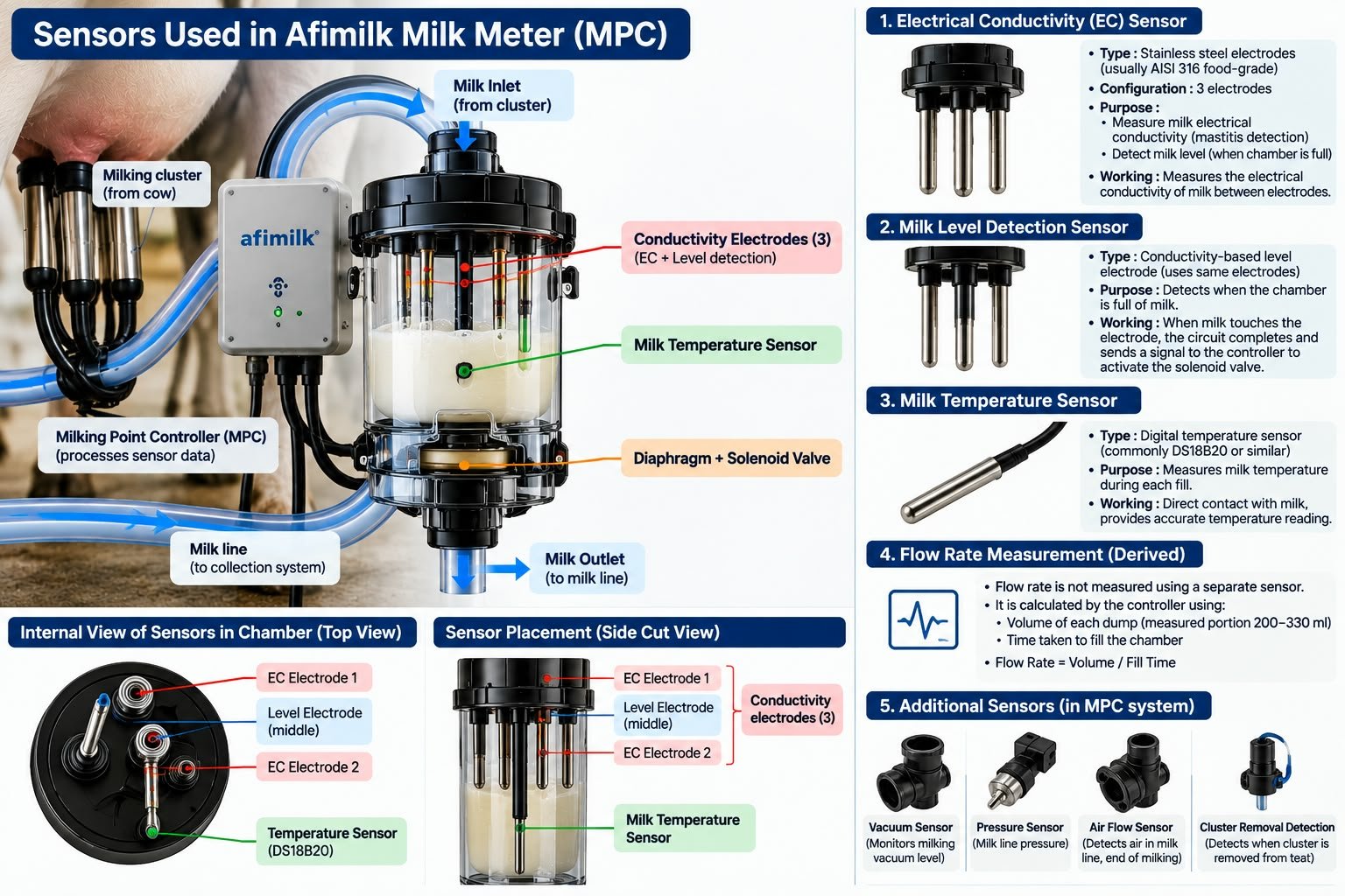
This project builds a real-time mastitis detection chamber that monitors milk electrical conductivity and temperature during milking. Mastitis causes inflammatory changes that raise milk conductivity, and this system detects abnormal rises to alert the operator immediately. The guide provides a complete wiring diagram, parts list, firmware, and step-by-step assembly instructions for integrating the 316L sanitary sampling chamber, conductivity probe, temperature sensor, and local warning indicators.
The ESP32 reads conductivity via an ADS1115 ADC and temperature via a DS18B20 sensor, comparing results against a baseline to flag suspicious milk within seconds of collection. An LED and buzzer provide instant on-site notification. The firmware includes temperature compensation and calibration routines so the chamber can be cleaned and recalibrated between milkings, making it practical for dairy operations seeking early disease detection.
Wiring diagram

Gather all the parts
Assemble it in 5 steps
1. Build the milk-contact chamber
Use a 316L stainless-steel cylindrical chamber with a smooth internal flow path, two dairy quick-connect ends, and a removable top cap. Fit it as a small sidestream after the milking claw, not as a restriction in the main milk hose. Keep the chamber about 150–250 mL so it flushes quickly with milk and cleaning liquid.
- Use food-grade silicone hose and dairy-rated tri-clamp or quick-connect seals so the chamber can be removed without tools.
- Use a clear sample section only if it is food-contact rated and tolerant of hot alkaline and acid cleaning chemicals.
- Do not use sharp internal steps, threaded wetted joints, or narrow dead ends because trapped milk can spoil and contaminate the next milking.
- Do not put the chamber before the claw vacuum section or make the main milk hose narrower; that can disturb milking.
2. Fit the two probes
Install the conductivity probe and the DS18B20 probe in sealed top or side ports so their tips sit in the flowing milk but do not touch each other or block the outlet. Put the temperature probe immediately beside the conductivity probe because the controller corrects conductivity using that temperature.
- Use a removable, flush-faced K=1 conductivity probe and a stainless thermowell with a hygienic gasket.
- Keep the electronics and BNC/cable connectors outside the wash-down area in an IP65 enclosure.
- Only use food-contact-compatible stainless steel and seals in contact with milk; unsuitable plastics, glues, or metals can contaminate milk.
- Never immerse the ESP32 or exposed electrical connectors in the cleaning solution.
3. Wire the measurement electronics
Place the ESP32, ADS1115, conductivity transmitter, and resistors in a sealed enclosure. Connect EC transmitter VCC to 3V3 (power), GND to GND (ground), and AO to the 100 kΩ resistor. Connect the other end of the 100 kΩ resistor to ADS1115 AIN0 (measurement signal) and to one end of the 10 kΩ resistor; connect the other 10 kΩ resistor end to GND (ground). Connect ADS1115 VDD to 3V3 (power), GND to GND (ground), SDA to GPIO21 (data), and SCL to GPIO22 (data).
- This 100 kΩ/10 kΩ pair reduces a possible 5 V transmitter output to about 0.45 V at the ADC, protecting the 3.3 V electronics.
- Use screened cable for the conductivity probe cable and keep it away from motors and vacuum-pump wiring.
- Check the transmitter output range before power-on. If it can exceed the divider design assumption, change the divider after checking with a multimeter.
- All electronics grounds must connect together; a missing ground gives unstable readings.
4. Wire temperature and local warning parts
Connect DS18B20 VCC to 3V3 (power), GND to GND (ground), and DATA to GPIO4 (signal). Connect the 4.7 kΩ pull-up resistor between 3V3 and the DS18B20 DATA wire (keeps the temperature signal readable). Connect the green LED anode to GPIO25 (status signal) and its other leg to GND (ground). Connect buzzer SIGNAL to GPIO26 (alert signal) and GND to GND (ground).
- The LED module includes its current-limiting resistor in this design.
- Label each cow and scan/select that cow in the app before each milking so the data is attached to the correct animal.
- Make sure VCC and GND are not swapped — swapped power can damage the sensor or board.
- Do not treat the buzzer as a diagnosis: it means collect a clean sample and confirm with CMT/SCC and a veterinarian.
5. Clean, calibrate, and operate every milking
Before field use, run the farm’s normal approved CIP rinse, alkaline wash, rinse, acid wash if used, and final potable-water rinse through the chamber according to chemical supplier concentration, temperature, and contact-time instructions. Calibrate the conductivity probe with suitable reference standards, then record a healthy baseline separately for each cow and preferably each quarter. During milking, let the sidestream flush the chamber before recording; the ESP32 prints temperature-corrected conductivity and raises a local alert only when it rises above that cow’s saved baseline threshold.
- For the competition prototype, store every reading with cow ID, milking time, yield, parity, days in milk, activity/rumination, weather, hygiene score, CMT/SCC result, and veterinary diagnosis. These labels are what allow the AI model to learn a genuine 7–14 day forecast.
- Use conductivity trends from multiple milkings, not a single reading. The cloud model should combine this chamber signal with SCC/CMT, yield fall, animal activity, rumination, temperature, and hygiene data.
- CIP compatibility must be validated using the exact probe, gasket, hose, and chemical supplier documentation before connecting it to saleable milk.
- A risk score must trigger verification and advice, not automatic antibiotic treatment.
Review all connections
1. Connections between "milk_chamber_1" and "ESP32"
2. Connections between "ec_sensor_1" and "ESP32"
3. Connections between "ads1115_1" and "ESP32"
4. Connections between "ds18b20_1" and "ESP32"
5. Connections between "onewire_pullup_1" and "ESP32"
6. Connections between "ec_divider_top_1" and "ESP32"
7. Connections between "ec_divider_bottom_1" and "ESP32"
8. Connections between "status_led_1" and "ESP32"
9. Connections between "alert_buzzer_1" and "ESP32"
Deploy the firmware
#include <Arduino.h>
#include <Wire.h>
#include <Adafruit_ADS1X15.h>
#include <OneWire.h>
#include <DallasTemperature.h>

constexpr int ONEWIRE_PIN = 4;
constexpr int STATUS_LED_PIN = 25;
constexpr int BUZZER_PIN = 26;
constexpr int I2C_SDA_PIN = 21;
constexpr int I2C_SCL_PIN = 22;
constexpr unsigned long SAMPLE_PERIOD_MS = 5000UL;

// Calibrate these two values with your known milk/reference samples.
constexpr float EC_CAL_SLOPE = 1.00f;
constexpr float EC_CAL_OFFSET_MS_CM = 0.00f;
constexpr float TEMP_REFERENCE_C = 25.0f;
constexpr float TEMP_COEFFICIENT = 0.019f;
constexpr float BASELINE_EC_MS_CM = 5.50f;
constexpr float HIGH_RISE_PERCENT = 12.0f;

Adafruit_ADS1115 ads;
OneWire oneWire(ONEWIRE_PIN);
DallasTemperature temperatureSensor(&oneWire);
unsigned long lastSampleMs = 0;

float readConductivityMilliSiemens(float temperatureC) {
  int16_t raw = ads.readADC_SingleEnded(0);
  float adcVoltage = raw * 0.000125f;  // ADS1115 gain-one volts per count.
  // Hardware divider is 100k over 10k: module voltage = ADC voltage x 11.
  float transmitterVoltage = adcVoltage * 11.0f;
  float uncorrectedEc = transmitterVoltage * EC_CAL_SLOPE + EC_CAL_OFFSET_MS_CM;
  float correction = 1.0f + TEMP_COEFFICIENT * (temperatureC - TEMP_REFERENCE_C);
  if (correction <= 0.05f) correction = 1.0f;
  return uncorrectedEc / correction;
}

void indicateRisk(bool highRisk) {
  digitalWrite(STATUS_LED_PIN, highRisk ? HIGH : LOW);
  if (highRisk) {
    tone(BUZZER_PIN, 2400, 180);
  }
}

void setup() {
  Serial.begin(115200);
  pinMode(STATUS_LED_PIN, OUTPUT);
  pinMode(BUZZER_PIN, OUTPUT);
  digitalWrite(STATUS_LED_PIN, LOW);

  Wire.begin(I2C_SDA_PIN, I2C_SCL_PIN);
  if (!ads.begin(0x48)) {
    Serial.println("FAULT,ADS1115 not found; check SDA GPIO21 and SCL GPIO22");
    while (true) {
      digitalWrite(STATUS_LED_PIN, !digitalRead(STATUS_LED_PIN));
      delay(250);
    }
  }
  ads.setGain(GAIN_ONE);
  temperatureSensor.begin();
  Serial.println("timestamp_ms,temp_c,ec_25c_ms_cm,ec_change_percent,risk,action");
}

void loop() {
  unsigned long now = millis();
  if (now - lastSampleMs < SAMPLE_PERIOD_MS) return;
  lastSampleMs = now;

  temperatureSensor.requestTemperatures();
  float temperatureC = temperatureSensor.getTempCByIndex(0);
  if (temperatureC == DEVICE_DISCONNECTED_C || temperatureC < 0.0f || temperatureC > 60.0f) {
    Serial.println("FAULT,temperature probe invalid; inspect chamber thermowell and GPIO4 wire");
    indicateRisk(true);
    return;
  }

  float ec = readConductivityMilliSiemens(temperatureC);
  float changePercent = 100.0f * (ec - BASELINE_EC_MS_CM) / BASELINE_EC_MS_CM;
  bool highRisk = changePercent >= HIGH_RISE_PERCENT;
  indicateRisk(highRisk);

  Serial.printf("%lu,%.2f,%.3f,%.1f,%s,%s\n", now, temperatureC, ec, changePercent,
                highRisk ? "HIGH" : "NO_ALERT",
                highRisk ? "take aseptic quarter sample; perform CMT/SCC and contact veterinarian" : "continue monitoring");
}
Remix this project
Make it yours in one click
Open a full copy of this project in your own Schematik workspace — diagram, code, parts, and assembly steps included. Swap the sensor, add features, or redesign the whole thing with AI. The author's original stays untouched.