Community project
12V Electrical Incident Recorder
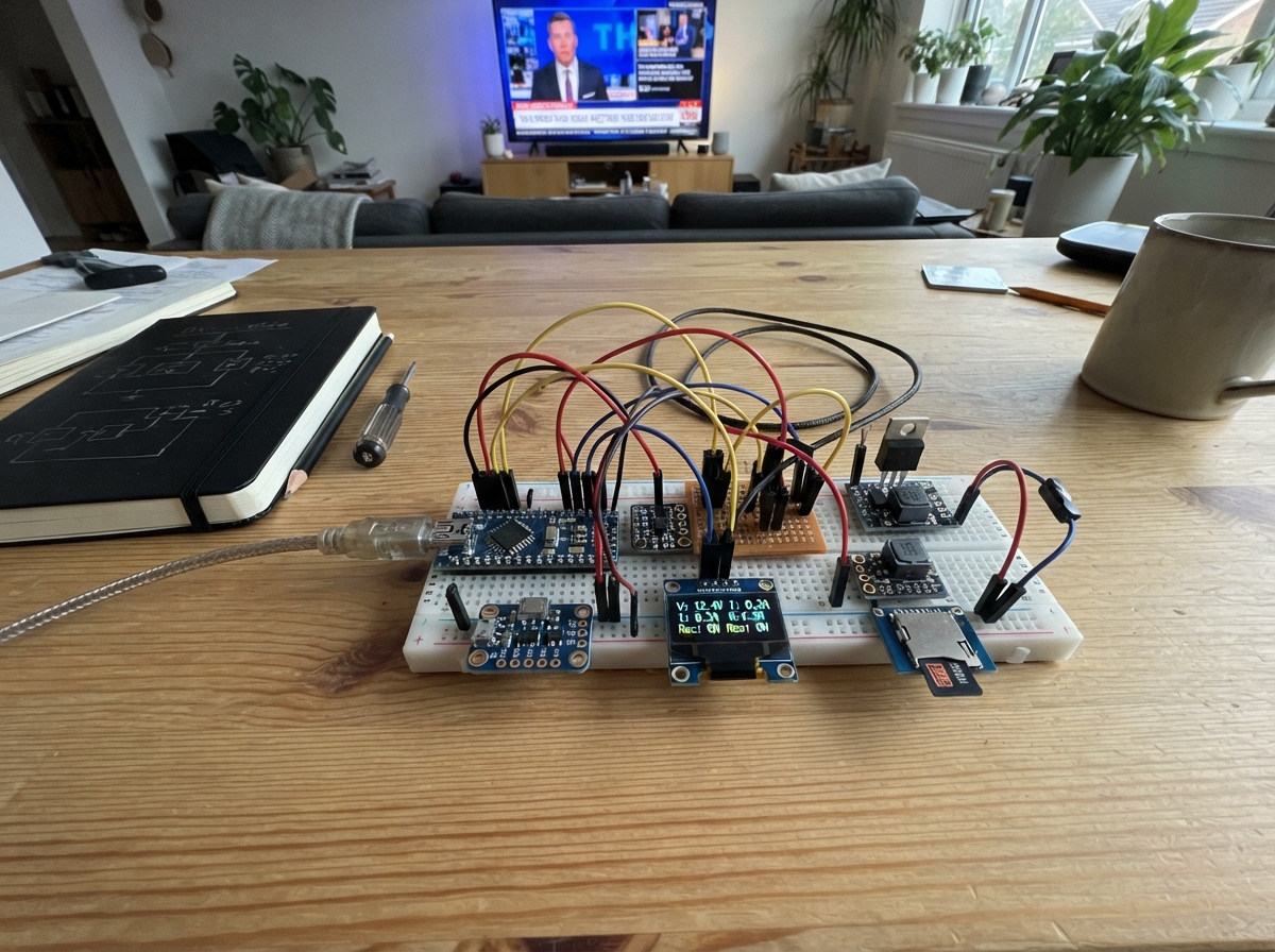
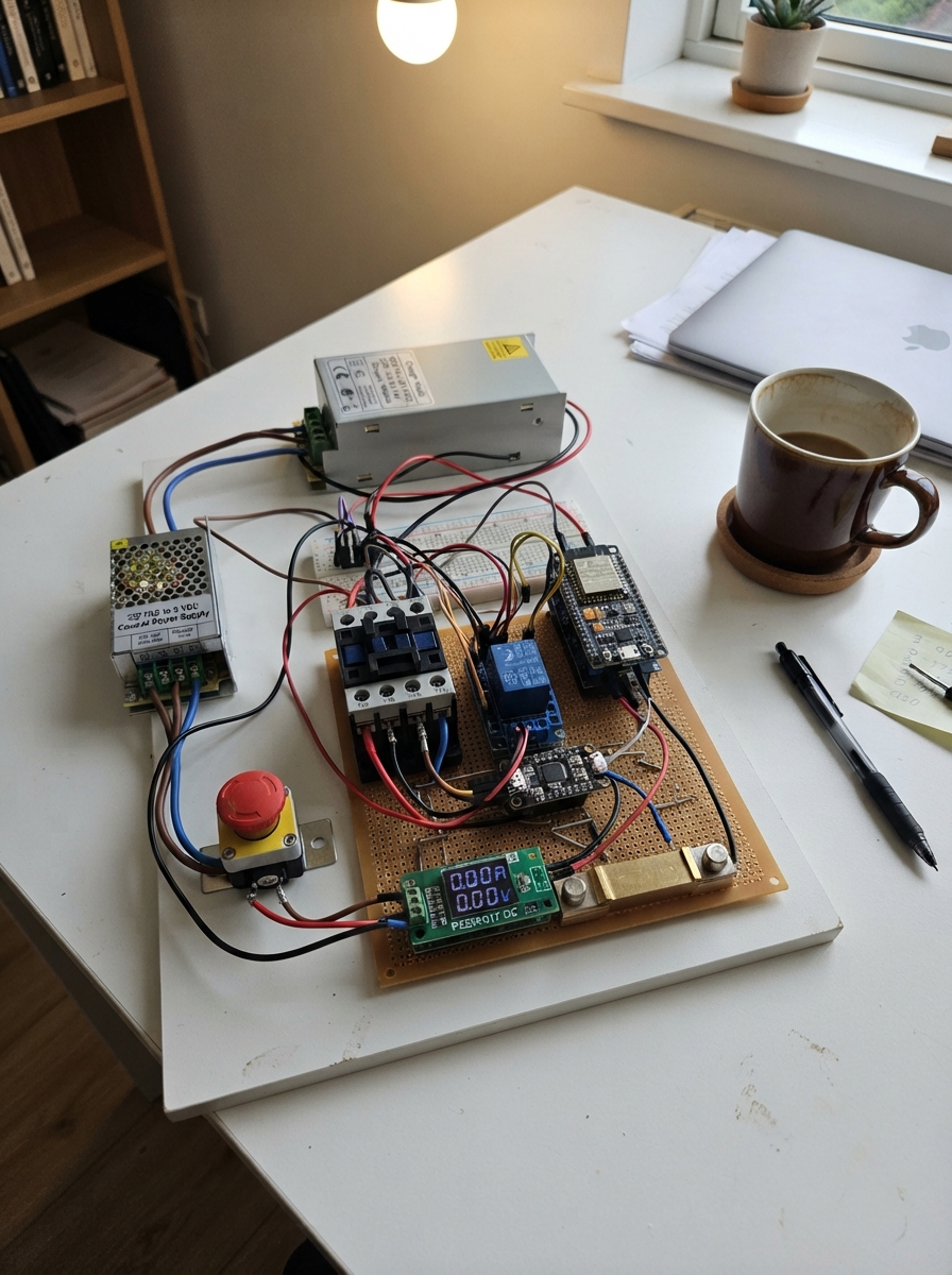
This project builds a comprehensive 12V electrical incident recorder that captures voltage, current, temperature, and motion data when anomalies occur. The system monitors a 12V power supply for faults like overvoltage, undervoltage, overcurrent, and mechanical disturbances, then logs detailed pre-event and post-event data to a microSD card for analysis.
The guide provides a complete wiring diagram, parts list, and step-by-step assembly instructions for building the protected 12V input stage, power distribution to the ESP32 and sensors, and the dual load-switching circuit. Firmware is included to sample the INA219 current sensor, ADS1115 ADC, MPU-6050 accelerometer, and thermistors at 10 Hz, display live readings on the SSD1306 OLED, and automatically record incidents with 5 seconds of pre-event and post-event context.
Wiring diagram

Gather all the parts
Assemble it in 9 steps
1. Keep the demonstration safely low voltage
Use an isolated regulated 12 V DC bench supply or plug-pack only. Leave it unplugged while wiring. Connect the positive lead to J1 POS and the negative lead to J1 NEG; this is the only external supply for the test circuit.
- Set the supply current limit to 1.0 A for the first power-up.
- Do not connect J1 to 230 V AC mains or any non-isolated mains-derived wiring; doing so can cause lethal shock and destroy the prototype.
2. Build the protected 12 V input
Wire J1 POS to F1 IN, F1 OUT to the unstriped anode end of D1, and D1's striped cathode to the protected +12V_PROT rail. Connect TVS1 cathode to +12V_PROT and its anode to GND. Connect C1 positive to +12V_PROT and C1 negative to GND.
- The stripe on the SS34 diode is the cathode end. The marked negative stripe on the electrolytic capacitor goes to GND.
- Reversing the electrolytic capacitor can make it overheat or burst.
3. Set up the 5 V and 3.3 V electronics power
Before connecting the ESP32, set the LM2596 buck module output to exactly 5.0 V with a multimeter. Connect buck VIN+ to +12V_PROT and VIN− to GND, then VOUT+ to the ESP32 5V/VIN pin and VOUT− to ESP32 GND. The ESP32's 3V3 pin supplies the sensors and card; connect C3 from 3V3 to GND close to the sensor bus.
- Use a buck converter rated for at least 2 A even though the logic electronics normally use far less; it runs cooler and has startup margin.
- Do not feed the protected 12 V rail into the ESP32 5V/VIN pin; that can permanently damage the board.
4. Wire the shared sensor and display wires
Connect every I2C module's SDA pin to ESP32 GPIO21 and every SCL pin to GPIO22: INA219, ADS1115, MPU6050, and OLED. Connect each module's GND to GND and each module's VCC/VDD/VIN to 3V3. Wire ADS1115 ADDR to GND so it uses address 0x48.
- Power all I2C modules from 3.3 V so their signal pull-up resistors never put 5 V onto the ESP32 pins.
- Make sure VCC and GND are not swapped on any module — swapped power can damage a sensor or OLED.
5. Put the current sensor in series with the loads
Connect +12V_PROT to INA219 VIN+. From INA219 VIN− make the +12V_LOAD rail. Connect one end of each 24 Ω resistor to +12V_LOAD. This puts all test-load current through the INA219 so it can measure voltage, current, and power.
- The two 24 Ω resistors draw about 0.5 A each at 12 V; with both on the total is about 1 A, so use 10 W resistors and leave air around them.
- The resistors become hot during the overload demonstration; keep wires and fingers away until they cool.
6. Wire the two low-side load switches
Connect the free end of the main resistor to the drain of mosfet_main and its source to GND. Connect GPIO25 through the 100 Ω R_GATE_MAIN resistor to its gate, and place its 100 kΩ pulldown from gate to GND. Repeat with the overload resistor, mosfet_overload, GPIO26, its 100 Ω resistor, and its 100 kΩ pulldown.
- For the TO-220 IRLZ44N, check the package printing and datasheet before soldering: looking at the front face with leads down is commonly Gate–Drain–Source from left to right.
- A MOSFET installed with drain and source swapped may not switch the load correctly and can overheat.
7. Build the temperature and voltage measurement inputs
For each NTC, connect its VCC lead to 3V3 and its GND lead to the A end of its matching 10 kΩ resistor; connect that resistor's B end to GND. Connect the load NTC SIG junction to ADS1115 AIN0 and the input NTC SIG junction to AIN1. For voltage monitoring, wire +12V_PROT to the 100 kΩ resistor, then to the 27 kΩ resistor to GND. From their junction pass through the 1 kΩ resistor to ADS1115 AIN2; connect the 3.3 V Zener cathode and 100 nF capacitor to that AIN2 side, with their other ends at GND.
- Place the load NTC close to, but not electrically touching, the hot main resistor; place the other beside J1 and the fuse.
- Do not connect the 12 V rail directly to an ADS1115 input; the divider and protection parts are what keep the ADC safe.
8. Connect the microSD card and finish the ground wiring
Use a microSD module that is explicitly 3.3 V compatible. Connect VCC to 3V3 and GND to GND. Connect SCK to GPIO18, MISO to GPIO19, MOSI to GPIO23, and CS to GPIO4. Join all module grounds, buck negative, and MOSFET sources at a short, thick ground point near the 12 V input, while keeping the small sensor ground wires separate from the high-current load return until that point.
- Format the card as FAT32 before inserting it. Keep SPI leads short, especially SCK.
- Some inexpensive microSD boards expect 5 V and may drive MISO at 5 V; use a module labelled 3.3 V compatible to avoid damaging the ESP32.
9. Check before powering and run the demonstration
With the supply still off, inspect for solder bridges and check that no 12 V wire reaches an ESP32 or sensor signal pin. Insert the microSD card, power from the isolated 12 V supply, then plug the ESP32 into USB for programming. The main load turns on after startup; once per minute the firmware briefly enables the second load to create a controlled event and writes EVENT_###.CSV to the card.
- The OLED should show NORMAL, voltage, current, temperatures, and the event number. After an event it should show INCIDENT RECORDED.
- If the fuse opens, power down first and find the wiring fault; never bypass the fuse with wire or foil.
Review all connections
1. Connections between "j1_12v_input" and "ESP32"
2. Connections between "f1_input" and "ESP32"
3. Connections between "d1_reverse" and "ESP32"
4. Connections between "tvs1" and "ESP32"
5. Connections between "c_12v_bulk" and "ESP32"
6. Connections between "buck_5v" and "ESP32"
7. Connections between "ina219_1" and "ESP32"
8. Connections between "ads1115_1" and "ESP32"
9. Connections between "mpu6050_1" and "ESP32"
10. Connections between "oled_1" and "ESP32"
11. Connections between "microsd_1" and "ESP32"
12. Connections between "ntc_load" and "ESP32"
13. Connections between "r_ntc_load" and "ESP32"
14. Connections between "ntc_input" and "ESP32"
15. Connections between "r_ntc_input" and "ESP32"
16. Connections between "r_div_top" and "ESP32"
17. Connections between "r_div_bottom" and "ESP32"
18. Connections between "r_adc_series" and "ESP32"
19. Connections between "zener_adc" and "ESP32"
20. Connections between "c_adc_filter" and "ESP32"
21. Connections between "c_3v3_bulk" and "ESP32"
22. Connections between "rload_main" and "ESP32"
23. Connections between "mosfet_main" and "ESP32"
24. Connections between "r_gate_main" and "ESP32"
25. Connections between "r_pd_main" and "ESP32"
26. Connections between "rload_overload" and "ESP32"
27. Connections between "mosfet_overload" and "ESP32"
28. Connections between "r_gate_overload" and "ESP32"
29. Connections between "r_pd_overload" and "ESP32"
Deploy the firmware
#include <Wire.h>
#include <SPI.h>
#include <SD.h>
#include <Adafruit_INA219.h>
#include <Adafruit_ADS1X15.h>
#include <Adafruit_GFX.h>
#include <Adafruit_SSD1306.h>
#include <MPU6050.h>
#include <math.h>

constexpr int I2C_SDA_PIN = 21;
constexpr int I2C_SCL_PIN = 22;
constexpr int SD_CS_PIN = 4;
constexpr int SD_SCK_PIN = 18;
constexpr int SD_MISO_PIN = 19;
constexpr int SD_MOSI_PIN = 23;
constexpr int MAIN_LOAD_GATE_PIN = 25;
constexpr int OVERLOAD_GATE_PIN = 26;

constexpr uint8_t OLED_ADDRESS = 0x3C;
constexpr uint16_t SAMPLE_PERIOD_MS = 100;
constexpr uint16_t DISPLAY_PERIOD_MS = 500;
constexpr uint8_t PRE_EVENT_SAMPLES = 50;   // 5 seconds at 10 Hz
constexpr uint8_t POST_EVENT_SAMPLES = 50;  // 5 seconds at 10 Hz
constexpr float LOW_VOLTAGE_V = 10.5f;
constexpr float HIGH_VOLTAGE_V = 13.5f;
constexpr float OVERCURRENT_A = 0.85f;
constexpr float DISTURBANCE_G = 1.60f;
constexpr float NTC_BETA = 3950.0f;
constexpr float NTC_R0 = 10000.0f;
constexpr float NTC_T0_K = 298.15f;

struct Sample {
  uint32_t timestampMs;
  float busVoltageV;
  float currentA;
  float powerW;
  float loadTempC;
  float inputTempC;
  float dividerVoltageV;
  float accelG;
};

Adafruit_INA219 ina219(0x40);
Adafruit_ADS1115 ads;
Adafruit_SSD1306 display(128, 64, &Wire, -1);
MPU6050 mpu;

Sample preBuffer[PRE_EVENT_SAMPLES];
Sample eventBuffer[PRE_EVENT_SAMPLES + POST_EVENT_SAMPLES];
uint8_t preHead = 0;
uint8_t preCount = 0;
uint8_t postCount = 0;
uint16_t eventCount = 0;
bool sdReady = false;
bool recordingEvent = false;
bool overloadOn = false;
uint32_t lastSampleMs = 0;
uint32_t lastDisplayMs = 0;
uint32_t lastDemoMs = 0;
String statusText = "NORMAL";
Sample latest = {};

float thermistorC(int16_t raw) {
  if (raw <= 0 || raw >= 32760) return NAN;
  const float voltage = ads.computeVolts(raw);
  if (voltage <= 0.001f || voltage >= 3.299f) return NAN;
  // NTC is connected to 3.3 V and the fixed 10 k resistor is connected to ground.
  const float resistance = 10000.0f * voltage / (3.3f - voltage);
  const float kelvin = 1.0f / ((1.0f / NTC_T0_K) + log(resistance / NTC_R0) / NTC_BETA);
  return kelvin - 273.15f;
}

Sample readSample() {
  Sample s = {};
  s.timestampMs = millis();
  s.busVoltageV = ina219.getBusVoltage_V();
  s.currentA = ina219.getCurrent_mA() / 1000.0f;
  s.powerW = ina219.getPower_mW() / 1000.0f;
  s.loadTempC = thermistorC(ads.readADC_SingleEnded(0));
  s.inputTempC = thermistorC(ads.readADC_SingleEnded(1));
  s.dividerVoltageV = ads.computeVolts(ads.readADC_SingleEnded(2)) * (127.0f / 27.0f);

  int16_t ax, ay, az, gx, gy, gz;
  mpu.getMotion6(&ax, &ay, &az, &gx, &gy, &gz);
  const float x = ax / 16384.0f;
  const float y = ay / 16384.0f;
  const float z = az / 16384.0f;
  s.accelG = sqrtf(x * x + y * y + z * z);
  return s;
}

bool abnormal(const Sample &s) {
  return s.busVoltageV < LOW_VOLTAGE_V || s.busVoltageV > HIGH_VOLTAGE_V ||
         fabsf(s.currentA) > OVERCURRENT_A || s.accelG > DISTURBANCE_G;
}

void appendPre(const Sample &s) {
  preBuffer[preHead] = s;
  preHead = (preHead + 1) % PRE_EVENT_SAMPLES;
  if (preCount < PRE_EVENT_SAMPLES) preCount++;
}

void beginEvent(const Sample &trigger) {
  eventCount++;
  const uint8_t oldest = (preHead + PRE_EVENT_SAMPLES - preCount) % PRE_EVENT_SAMPLES;
  for (uint8_t i = 0; i < preCount; ++i) {
    eventBuffer[i] = preBuffer[(oldest + i) % PRE_EVENT_SAMPLES];
  }
  eventBuffer[preCount] = trigger;
  postCount = 1;
  recordingEvent = true;
  statusText = "EVENT DETECTED";
}

void saveEvent() {
  if (!sdReady) {
    statusText = "SD ERROR";
    recordingEvent = false;
    return;
  }
  char filename[24];
  snprintf(filename, sizeof(filename), "/EVENT_%03u.CSV", eventCount);
  File file = SD.open(filename, FILE_WRITE);
  if (!file) {
    statusText = "SD WRITE ERROR";
    recordingEvent = false;
    return;
  }
  file.println("event_number,uptime_ms,bus_voltage_V,current_A,power_W,load_temp_C,input_temp_C,divider_voltage_V,accel_g");
  const uint16_t total = preCount + postCount;
  for (uint16_t i = 0; i < total; ++i) {
    const Sample &s = eventBuffer[i];
    file.printf("%u,%lu,%.3f,%.4f,%.3f,%.2f,%.2f,%.3f,%.3f\n", eventCount,
                static_cast<unsigned long>(s.timestampMs), s.busVoltageV, s.currentA,
                s.powerW, s.loadTempC, s.inputTempC, s.dividerVoltageV, s.accelG);
  }
  file.close();
  statusText = "INCIDENT RECORDED";
  recordingEvent = false;
}

void drawDisplay() {
  display.clearDisplay();
  display.setTextSize(1);
  display.setTextColor(SSD1306_WHITE);
  display.setCursor(0, 0);
  display.println(statusText);
  display.printf("V: %.2f V  I: %.3f A\n", latest.busVoltageV, latest.currentA);
  display.printf("T1: %.1fC T2: %.1fC\n", latest.loadTempC, latest.inputTempC);
  display.printf("Event: %u  SD:%s\n", eventCount, sdReady ? "OK" : "ERR");
  display.printf("a: %.2f g", latest.accelG);
  display.display();
}

void setup() {
  pinMode(MAIN_LOAD_GATE_PIN, OUTPUT);
  pinMode(OVERLOAD_GATE_PIN, OUTPUT);
  digitalWrite(MAIN_LOAD_GATE_PIN, LOW);
  digitalWrite(OVERLOAD_GATE_PIN, LOW);

  Serial.begin(115200);
  Wire.begin(I2C_SDA_PIN, I2C_SCL_PIN);
  ina219.begin();
  ads.setGain(GAIN_ONE); // ±4.096 V input range; all applied ADC signals are 0–3.3 V.
  ads.begin(0x48);
  mpu.initialize();
  display.begin(SSD1306_SWITCHCAPVCC, OLED_ADDRESS);
  display.clearDisplay();
  display.display();

  SPI.begin(SD_SCK_PIN, SD_MISO_PIN, SD_MOSI_PIN, SD_CS_PIN);
  sdReady = SD.begin(SD_CS_PIN, SPI);
  digitalWrite(MAIN_LOAD_GATE_PIN, HIGH); // Primary 24 ohm test load enabled for the demonstration.
  statusText = sdReady ? "NORMAL" : "SD ERROR";
}

void loop() {
  const uint32_t now = millis();

  // Once per minute, add the second 24 ohm load for three seconds to demonstrate a controlled overload incident.
  if (!recordingEvent && now - lastDemoMs >= 60000UL) {
    lastDemoMs = now;
    overloadOn = true;
    digitalWrite(OVERLOAD_GATE_PIN, HIGH);
  }
  if (overloadOn && now - lastDemoMs >= 3000UL) {
    overloadOn = false;
    digitalWrite(OVERLOAD_GATE_PIN, LOW);
  }

  if (now - lastSampleMs >= SAMPLE_PERIOD_MS) {
    lastSampleMs = now;
    latest = readSample();
    if (!recordingEvent) {
      appendPre(latest);
      if (abnormal(latest)) beginEvent(latest);
    } else {
      if (postCount < POST_EVENT_SAMPLES) {
        eventBuffer[preCount + postCount] = latest;
        postCount++;
      }
      if (postCount >= POST_EVENT_SAMPLES) saveEvent();
    }
  }

  if (now - lastDisplayMs >= DISPLAY_PERIOD_MS) {
    lastDisplayMs = now;
    drawDisplay();
  }
}
Remix this project
Make it yours in one click
Open a full copy of this project in your own Schematik workspace — diagram, code, parts, and assembly steps included. Swap the sensor, add features, or redesign the whole thing with AI. The author's original stays untouched.