Community project
High-Altitude Telemetry Payload
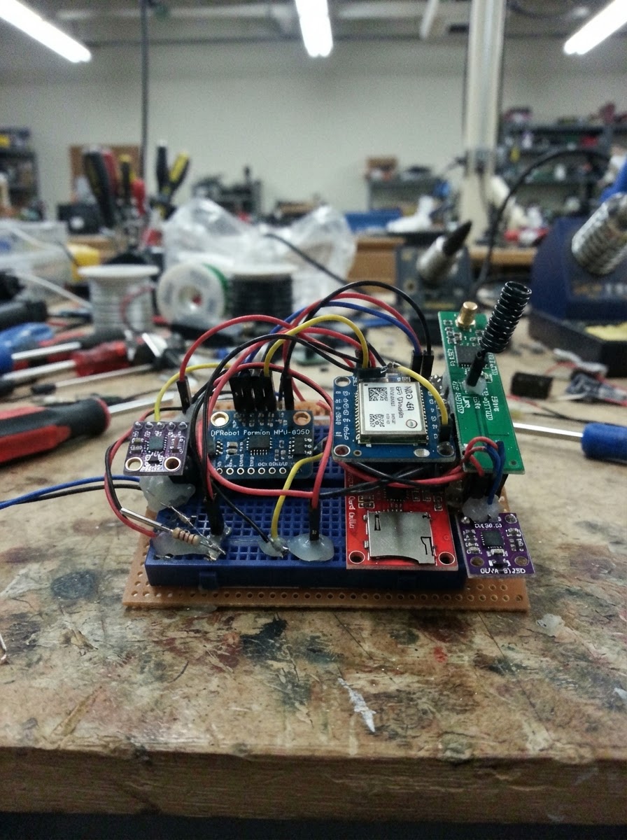
This high-altitude telemetry payload captures environmental and motion data during balloon or rocket flights up to 18 km. Built around an ESP32 microcontroller, it combines a BME280 environmental sensor, MPU-6050 6-axis IMU, NEO-6M GPS module, UV intensity sensor, and DS18B20 temperature probe to log altitude, pressure, humidity, acceleration, rotation, position, and radiation data to a MicroSD card while transmitting live telemetry via LoRa radio.
This guide provides a complete wiring diagram, parts list, and step-by-step assembly instructions for integrating the sensor bus, communication modules, and power system into a flight-ready payload. You'll also get the Arduino firmware that initializes all sensors, manages data logging, and handles LoRa transmission, plus mechanical testing procedures to verify the build before launch.
Wiring diagram

Gather all the parts
Assemble it in 6 steps
1. Prepare the insulated payload and power system
Use a protected 2S (7.4 V nominal) LiPo battery, not a single 3.7 V cell, because buck_1 is step-down only. Connect battery_1 BAT+ to buck_1 VIN and battery_1 BAT− to buck_1 GND. Before any electronics are attached, measure buck_1 VOUT relative to GND and adjust it to exactly 5.0 V. Feed that 5 V output to the ESP32 DevKit V1 VIN/5V pin and connect its ground to the common ground rail. Keep the battery, regulator, and all cables inside the insulated enclosure; strain-relieve every cable.
- Choose a 2200–3000 mAh protected 2S pack with a suitable connector and a charger specifically rated for 2S lithium packs.
- Add an inline fuse close to the battery positive lead if available.
- Keep the MP1584 away from the BME280 and GPS antenna to reduce heat and electrical noise.
- Never connect a 3.7 V single-cell LiPo directly to buck_1 expecting 5 V output; this regulator cannot boost voltage.
- Do not connect the camera or ESP32 until the buck output has been checked with a multimeter.
- Do not charge a LiPo inside a sealed foam payload or while unattended.
2. Build the common 3.3 V sensor bus
With the ESP32 unpowered, join every sensor ground to an ESP32 GND pin. Use the ESP32 3V3 pin for the logic/sensor rail: connect bme280_1 VCC, mpu6050_1 VIN, gps_1 VCC, sd_1 VCC, ds18b20_1 VCC, lora_1 VCC, and guva_1 VCC to 3V3. Connect each corresponding GND pin to GND. This design intentionally runs all listed modules at 3.3 V to protect ESP32 GPIO.
- Use short twisted or paired ground/signal wires where practical, especially for I2C and the radio supply.
- Add a local electrolytic capacitor near lora_1 VCC/GND if its breakout does not already have adequate decoupling.
- Never connect the E32 UART pins or the GUVA output to 5 V when attached to the ESP32.
- Some low-cost MicroSD boards are intended for 5 V Arduino systems. Use a module proven to accept 3.3 V supply and 3.3 V SPI logic.
3. Wire the shared I2C environmental and motion sensors
Connect bme280_1 SDA and mpu6050_1 SDA together at ESP32 GPIO21. Connect bme280_1 SCL and mpu6050_1 SCL together at ESP32 GPIO22. Leave the optional interrupt pins unconnected. Mount bme280_1 where it samples outside air through a protected vent and breathable mesh; keep it away from the warm-water container and regulator.
- The BME280 must not be sealed in the warm electronics cavity if you need external atmospheric pressure and humidity readings.
- Secure mpu6050_1 firmly to the payload structure so its axes do not move relative to the payload.
- Do not use a BME280 and a second I2C device with the same address unless you deliberately change one address; the MPU-6050 default address is different and is safe on this bus.
- Protect the BME280 vent from liquid water and direct debris; do not cover the sensor opening with tape.
4. Wire the GPS, MicroSD, DS18B20, and UV sensor
Connect gps_1 TX to ESP32 GPIO16 and gps_1 RX to GPIO17. Connect sd_1 MISO to GPIO19, MOSI to GPIO23, SCK to GPIO18, and CS to GPIO13. Connect ds18b20_1 DATA to GPIO4. Install onewire_pullup_1 between the same DS18B20 DATA point and 3V3 (it is not connected to ground). Connect guva_1 OUT to GPIO34, which is input-only and suitable for analog sensing. Tape the DS18B20 probe directly against the battery pack with electrical insulation over the probe and tape.
- Use a quality, freshly formatted high-endurance MicroSD card and physically secure it in sd_1.
- Mount the GPS patch antenna facing outward with as much sky view as possible, separated from the radio antenna and buck converter.
- Place the GUVA-S12SD behind a UV-transparent opening; ordinary glass and many plastics attenuate UV.
- The 4.7 kΩ onewire_pullup_1 must go from DATA to 3.3 V; connecting it to ground prevents the DS18B20 bus from working.
- GPIO34 has no internal pull-up; that is correct for the GUVA analog output.
- NEO-6M devices are subject to their own firmware limits and may cease navigation at high altitude/high dynamics; this project does not override those limits.
5. Wire the E32 radio and its antenna
Connect lora_1 TXD to ESP32 GPIO26, lora_1 RXD to GPIO25, and lora_1 AUX to GPIO27. Tie lora_1 M0 and M1 to GND to select normal transparent UART mode. Attach the antenna designed for the exact legally authorized 433 MHz operating frequency before powering the transmitter. Keep the antenna clear of the GPS patch antenna, battery, and conductive foil.
- The E32 must share ground with the ESP32; a UART connection alone is not sufficient.
- Route the radio antenna vertically outside the foam enclosure and provide mechanical strain relief at the module.
- Use the matching E32 settings on the ground-station receiver: air data rate, channel, UART rate, parity, and address must agree.
- Do not transmit without an antenna attached; it can stress the radio output stage.
- Confirm that 433 MHz operation, output power, bandwidth, duty cycle, telemetry content, and antenna use are permitted at your launch location before flight.
- The stated 16.4 cm per side dipole dimension should be verified with a proper 433 MHz antenna design and local regulations; antenna length and feedline arrangement materially affect performance.
6. Install and test mechanically before flight
Mount the electronics on a nonconductive plate, secure the MicroSD card, and ensure no bare metal can contact the battery. Place the sealed hot-water container in a separate compartment from the electronics, with an additional waterproof barrier. Ensure the BME280 vent, GUVA window, GPS sky view, and radio antenna path remain unobstructed. Verify the parachute/recovery system is fully independent of the ESP32 firmware. Power the payload from its regulated 5 V input and use Schematik’s Deploy button to load the firmware after the wiring is inspected.
- Bench-test for several hours with the complete power system and radio transmission enabled; inspect the CSV log for a new row every two seconds.
- Use conformal protection or enclosed mounting appropriate to condensation risk, while leaving the pressure sensor vent and optical sensor window functional.
- A separate audible/visual recovery beacon and a manual pre-flight checklist improve recovery robustness.
- Hot water can leak and burn; use a leak-tested, heat-rated sealed container and never allow it to contact a LiPo battery or electronics.
- High-altitude balloon launches may require aviation authority approval, radio authorization, and recovery planning. Follow all applicable rules and do not fly near controlled airspace.
- Do not rely on this telemetry system as the sole safety or recovery system.
Review all connections
1. Connections between "bme280_1" and "ESP32"
2. Connections between "mpu6050_1" and "ESP32"
3. Connections between "gps_1" and "ESP32"
4. Connections between "sd_1" and "ESP32"
5. Connections between "ds18b20_1" and "ESP32"
6. Connections between "onewire_pullup_1" and "ESP32"
7. Connections between "lora_1" and "ESP32"
8. Connections between "guva_1" and "ESP32"
9. Connections between "battery_1" and "ESP32"
10. Connections between "buck_1" and "ESP32"
Deploy the firmware
#include <Arduino.h>
#include <Wire.h>
#include <SPI.h>
#include <SD.h>
#include <Adafruit_BME280.h>
#include <OneWire.h>
#include <DallasTemperature.h>
#include <TinyGPSPlus.h>


// Forward declarations
void writeMpuRegister(uint8_t reg, uint8_t value);
bool readMpuWord(uint8_t reg, int16_t &value);
bool readImu(float &ax, float &ay, float &az, float &gx, float &gy, float &gz);
void appendLogHeaderIfNeeded();

constexpr int I2C_SDA_PIN = 21;
constexpr int I2C_SCL_PIN = 22;
constexpr int SD_CS_PIN = 13;
constexpr int ONEWIRE_PIN = 4;
constexpr int UV_PIN = 34;
constexpr int GPS_RX_PIN = 16;
constexpr int GPS_TX_PIN = 17;
constexpr int LORA_RX_PIN = 26;
constexpr int LORA_TX_PIN = 25;
constexpr int LORA_AUX_PIN = 27;
constexpr float GPS_TELEMETRY_CEILING_M = 18000.0f;
constexpr uint32_t SAMPLE_INTERVAL_MS = 2000;

Adafruit_BME280 bme;
OneWire oneWire(ONEWIRE_PIN);
DallasTemperature batteryProbe(&oneWire);
TinyGPSPlus gps;
HardwareSerial gpsSerial(2);
HardwareSerial loraSerial(1);

bool bmeReady = false;
bool sdReady = false;
uint32_t lastSampleMs = 0;

void writeMpuRegister(uint8_t reg, uint8_t value) {
  Wire.beginTransmission(0x68);
  Wire.write(reg);
  Wire.write(value);
  Wire.endTransmission();
}

bool readMpuWord(uint8_t reg, int16_t &value) {
  Wire.beginTransmission(0x68);
  Wire.write(reg);
  if (Wire.endTransmission(false) != 0) return false;
  if (Wire.requestFrom(0x68, 2) != 2) return false;
  value = (int16_t)((Wire.read() << 8) | Wire.read());
  return true;
}

bool readImu(float &ax, float &ay, float &az, float &gx, float &gy, float &gz) {
  int16_t rawAx, rawAy, rawAz, rawGx, rawGy, rawGz;
  bool ok = readMpuWord(0x3B, rawAx) && readMpuWord(0x3D, rawAy) &&
            readMpuWord(0x3F, rawAz) && readMpuWord(0x43, rawGx) &&
            readMpuWord(0x45, rawGy) && readMpuWord(0x47, rawGz);
  if (!ok) return false;
  ax = rawAx / 2048.0f;  // ±16 g
  ay = rawAy / 2048.0f;
  az = rawAz / 2048.0f;
  gx = rawGx / 16.4f;    // ±2000 degrees/s
  gy = rawGy / 16.4f;
  gz = rawGz / 16.4f;
  return true;
}

void appendLogHeaderIfNeeded() {
  if (!sdReady || SD.exists("/flight_log.csv")) return;
  File file = SD.open("/flight_log.csv", FILE_WRITE);
  if (file) {
    file.println("ms,pressure_hpa,air_temp_c,humidity_pct,baro_alt_m,battery_temp_c,uv_volts,uv_index,ax_g,ay_g,az_g,gx_dps,gy_dps,gz_dps,gps_lat,gps_lon,gps_alt_m,gps_valid");
    file.close();
  }
}

void setup() {
  Serial.begin(115200);
  Wire.begin(I2C_SDA_PIN, I2C_SCL_PIN);
  bmeReady = bme.begin(0x76) || bme.begin(0x77);

  // MPU-6050 awake, ±16 g accelerometer, ±2000 degrees/s gyro.
  writeMpuRegister(0x6B, 0x00);
  writeMpuRegister(0x1C, 0x18);
  writeMpuRegister(0x1B, 0x18);

  batteryProbe.begin();
  analogReadResolution(12);
  pinMode(LORA_AUX_PIN, INPUT);
  gpsSerial.begin(9600, SERIAL_8N1, GPS_RX_PIN, GPS_TX_PIN);
  loraSerial.begin(9600, SERIAL_8N1, LORA_RX_PIN, LORA_TX_PIN);
  sdReady = SD.begin(SD_CS_PIN);
  appendLogHeaderIfNeeded();

  Serial.println(bmeReady ? "BME280 ready" : "BME280 not detected");
  Serial.println(sdReady ? "SD logger ready" : "SD logger not detected");
}

void loop() {
  while (gpsSerial.available()) gps.encode(gpsSerial.read());
  const uint32_t now = millis();
  if (now - lastSampleMs < SAMPLE_INTERVAL_MS) return;
  lastSampleMs = now;

  float pressure = NAN, airTemp = NAN, humidity = NAN, baroAltitude = NAN;
  if (bmeReady) {
    pressure = bme.readPressure() / 100.0f;
    airTemp = bme.readTemperature();
    humidity = bme.readHumidity();
    baroAltitude = bme.readAltitude(1013.25f);
  }

  batteryProbe.requestTemperatures();
  const float batteryTemp = batteryProbe.getTempCByIndex(0);
  const float uvVolts = analogRead(UV_PIN) * (3.3f / 4095.0f);
  const int uvIndex = constrain((int)lroundf(uvVolts * 10.0f), 0, 15);

  float ax = NAN, ay = NAN, az = NAN, gx = NAN, gy = NAN, gz = NAN;
  readImu(ax, ay, az, gx, gy, gz);

  const bool belowCeiling = isfinite(baroAltitude) && baroAltitude < GPS_TELEMETRY_CEILING_M;
  const bool gpsAllowed = belowCeiling && gps.location.isValid() && gps.location.age() < 5000;
  const double lat = gpsAllowed ? gps.location.lat() : 0.0;
  const double lon = gpsAllowed ? gps.location.lng() : 0.0;
  const double gpsAlt = gpsAllowed && gps.altitude.isValid() ? gps.altitude.meters() : 0.0;

  char line[420];
  snprintf(line, sizeof(line), "%lu,%.2f,%.2f,%.2f,%.2f,%.2f,%.3f,%d,%.2f,%.2f,%.2f,%.1f,%.1f,%.1f,%.6f,%.6f,%.1f,%d",
           (unsigned long)now, pressure, airTemp, humidity, baroAltitude, batteryTemp,
           uvVolts, uvIndex, ax, ay, az, gx, gy, gz, lat, lon, gpsAlt, gpsAllowed ? 1 : 0);

  if (sdReady) {
    File file = SD.open("/flight_log.csv", FILE_APPEND);
    if (file) {
      file.println(line);
      file.close();
    } else {
      sdReady = false;
    }
  }

  // E32 M0/M1 are hard-wired low for transparent normal mode. AUX high means ready.
  if (digitalRead(LORA_AUX_PIN) == HIGH) loraSerial.println(line);
  Serial.println(line);
}
Remix this project
Make it yours in one click
Open a full copy of this project in your own Schematik workspace — diagram, code, parts, and assembly steps included. Swap the sensor, add features, or redesign the whole thing with AI. The author's original stays untouched.