Community project
Humidity-Temperature Motor Control
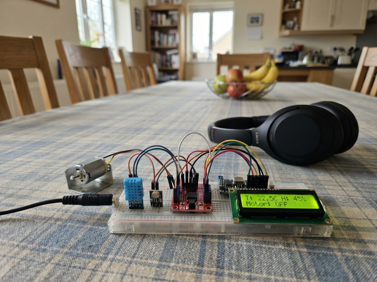
This project combines environmental sensing with motor control to create a system that monitors humidity and temperature while driving a 12V DC motor based on sensor input. The build uses an ESP32 microcontroller paired with a DHT11 sensor for climate data, a light sensor for additional environmental awareness, and an HC-160A dual motor driver to manage motor direction and speed. A 16x2 LCD display shows real-time readings, while a logic level shifter bridges communication between the ESP32 and the display.
Followers will receive a complete wiring diagram showing all sensor and motor connections, a full parts list with specifications, and step-by-step assembly instructions. The included firmware demonstrates how to read sensor values, control motor state (forward, reverse, stop), and update the LCD display at regular intervals. This guide is ideal for makers learning to integrate multiple sensors and actuators with an ESP32 in a single coordinated project.
Wiring diagram

Gather all the parts
Assemble it in 7 steps
1. Turn off power before changing the screen
Unplug the ESP32 USB cable and turn off the 12 V adapter before removing the old screen. This prevents a loose wire from touching the wrong place.
- Do not move display wires while power is connected — a short can damage the ESP32 or LCD.
2. Connect the DHT11 sensor
Connect DHT11 VCC to ESP32 3V3 (power), DHT11 GND to ESP32 GND (ground), and DHT11 DATA to GPIO4 (temperature and humidity signal).
- If yours is a bare four-pin DHT11 rather than a breakout board, add a 10 kΩ resistor from VCC to DATA so its signal stays reliable.
3. Wire the light sensor
Connect the light sensor VCC to ESP32 3V3 (power), GND to ESP32 GND (ground), and DO to GPIO23 (light signal). Keep this sensor on 3.3 V so its DO signal is safe for the ESP32.
- Turn the module's small adjustment screw slowly after power-up until its indicator and the LCD light reading change at the brightness you want.
- Do not connect the light sensor VCC to 5 V — its DO output could then be too high for GPIO23.
4. Wire the 16×2 LCD through the level shifter
Connect LCD VCC to the regulated 5 V buck output (power) and LCD GND to shared GND (ground). On the LCD level shifter, connect LV to ESP32 3V3 (power), HV to regulated 5 V (power), and GND to shared GND (ground). Connect LV1 to GPIO21 (LCD data), HV1 to LCD SDA (LCD data), LV2 to GPIO22 (LCD clock), and HV2 to LCD SCL (LCD clock).
- The LCD contrast screw is on the small board behind the screen. Turn it slowly after power-up until characters are visible.
- Keep the level shifter fitted: a 5 V LCD can place too much voltage on ESP32 data pins and damage the board if connected directly.
5. Keep the motor-control wiring in place
Keep the motor level shifter connected: LV to ESP32 3V3 (power), HV to regulated 5 V (power), GND to shared GND (ground), LV1 to GPIO25 (motor enable signal), LV2 to GPIO26 (direction signal), and LV3 to GPIO27 (direction signal). Its HV1, HV2, and HV3 wires go to PA, A, and B on the HC-160A.
- Keep the level shifter between the ESP32 and motor driver so motor-driver voltage cannot reach the ESP32 pins.
6. Connect the motor and 12 V supply
Connect motor M+ to HC-160A MOTOR_A+ (motor power) and motor M- to MOTOR_A- (motor return). Connect adapter +12V to HC-160A V+ (motor power) and adapter GND to HC-160A GND (ground). Keep adapter ground, ESP32 ground, buck-converter negative output, and HC-160A G joined (shared ground).
- Never connect the 12 V adapter to an ESP32 pin — 12 V will damage the board.
7. Power up and check the display
Before connecting it, use a meter to set the buck converter to exactly 5.0 V. Connect that output to the ESP32 VIN/5V input (power), plug the ESP32 into USB, then turn on the 12 V adapter. The 16×2 LCD shows temperature and humidity on the first line, then light and motor state on the second line.
- This firmware uses LCD I²C address 0x27. The motor turns on only above 30 C and 80% humidity; the light sensor is display-only.
- A buck-converter output above 5.0 V can damage the ESP32.
Review all connections
1. Connections between "dht11_1" and "ESP32"
2. Connections between "hc160a_1" and "ESP32"
3. Connections between "buck_5v_1" and "ESP32"
4. Connections between "level_shifter_motor_1" and "ESP32"
5. Connections between "level_shifter_lcd_1" and "ESP32"
6. Connections between "light_sensor_1" and "ESP32"
7. Connections between "lcd_16x2_1" and "ESP32"
Deploy the firmware
#include <Arduino.h>
#include <Wire.h>
#include <DHT.h>
#include <LiquidCrystal_I2C.h>

constexpr uint8_t DHT_PIN = 4;
constexpr uint8_t LIGHT_SENSOR_PIN = 23;
constexpr uint8_t MOTOR_ENABLE_PIN = 27;
constexpr uint8_t MOTOR_DIR_A_PIN = 14;
constexpr uint8_t MOTOR_DIR_B_PIN = 13;
constexpr uint8_t I2C_SDA_PIN = 21;
constexpr uint8_t I2C_SCL_PIN = 22;
constexpr uint8_t DHT_TYPE = DHT11;
constexpr uint8_t LCD_ADDRESS = 0x27;
constexpr unsigned long SAMPLE_INTERVAL_MS = 2000;
constexpr uint8_t MOTOR_PWM_50_PERCENT = 128;  // 128 / 255 is approximately 50% duty cycle.

DHT dht(DHT_PIN, DHT_TYPE);
LiquidCrystal_I2C lcd(LCD_ADDRESS, 16, 2);
unsigned long lastSampleMs = 0;

enum class MotorState { STOP, UP, DOWN };

void setMotor(MotorState state) {
  const bool motorRuns = state != MotorState::STOP;
  // The enable input receives a 50% PWM signal whenever the motor is commanded to move.
  analogWrite(MOTOR_ENABLE_PIN, motorRuns ? MOTOR_PWM_50_PERCENT : 0);
  digitalWrite(MOTOR_DIR_A_PIN, state == MotorState::UP ? HIGH : LOW);
  digitalWrite(MOTOR_DIR_B_PIN, state == MotorState::DOWN ? HIGH : LOW);
}

void printLine(uint8_t row, const char *text) {
  char padded[17];
  snprintf(padded, sizeof(padded), "%-16.16s", text);
  lcd.setCursor(0, row);
  lcd.print(padded);
}

const char *motorStateName(MotorState state) {
  if (state == MotorState::UP) return "UP";
  if (state == MotorState::DOWN) return "DOWN";
  return "STOP";
}

void showReadings(float temperatureC, float humidity, MotorState motorState, bool lightDetected) {
  char line1[17];
  char line2[17];
  snprintf(line1, sizeof(line1), "T:%.1fC H:%.0f%%", temperatureC, humidity);
  snprintf(line2, sizeof(line2), "L:%s M:%s", lightDetected ? "BRIGHT" : "DARK", motorStateName(motorState));
  printLine(0, line1);
  printLine(1, line2);
}

void showSensorError(bool lightDetected) {
  printLine(0, "DHT11 read failed");
  printLine(1, lightDetected ? "L:BRIGHT M:STOP" : "L:DARK M:STOP");
}

void setup() {
  Serial.begin(115200);
  pinMode(MOTOR_ENABLE_PIN, OUTPUT);
  analogWriteResolution(MOTOR_ENABLE_PIN, 8);
  analogWriteFrequency(MOTOR_ENABLE_PIN, 20000);
  pinMode(MOTOR_DIR_A_PIN, OUTPUT);
  pinMode(MOTOR_DIR_B_PIN, OUTPUT);
  pinMode(LIGHT_SENSOR_PIN, INPUT);
  setMotor(MotorState::STOP);

  dht.begin();
  Wire.begin(I2C_SDA_PIN, I2C_SCL_PIN);
  lcd.init();
  lcd.backlight();
  lcd.clear();
  printLine(0, "Humidity control");
  printLine(1, "Starting...");
}

void loop() {
  const unsigned long now = millis();
  if (now - lastSampleMs < SAMPLE_INTERVAL_MS) return;
  lastSampleMs = now;

  // Typical LM393 light-sensor modules pull DO LOW at the chosen light threshold.
  const bool lightDetected = digitalRead(LIGHT_SENSOR_PIN) == LOW;
  const float humidity = dht.readHumidity();
  const float temperatureC = dht.readTemperature();

  if (isnan(humidity) || isnan(temperatureC)) {
    setMotor(MotorState::STOP);
    Serial.printf("DHT11 read failed; light: %s; motor OFF\n", lightDetected ? "BRIGHT" : "DARK");
    showSensorError(lightDetected);
    return;
  }

  // Temperature has first priority, humidity second, and light third.
  MotorState motorState = MotorState::STOP;
  if (temperatureC > 30.0f) {
    motorState = MotorState::DOWN;
  } else if (temperatureC <= 28.0f) {
    motorState = MotorState::UP;
  } else if (humidity < 70.0f) {
    motorState = MotorState::DOWN;
  } else if (humidity >= 75.0f) {
    motorState = MotorState::UP;
  } else {
    // Light is the final tie-breaker: bright stops the motor; dark moves it up.
    motorState = lightDetected ? MotorState::STOP : MotorState::UP;
  }

  setMotor(motorState);
  Serial.printf("Temperature: %.1f C, Humidity: %.1f %%, Light: %s, Motor: %s\n",
                temperatureC, humidity, lightDetected ? "BRIGHT" : "DARK", motorStateName(motorState));
  showReadings(temperatureC, humidity, motorState, lightDetected);
}
Remix this project
Make it yours in one click
Open a full copy of this project in your own Schematik workspace — diagram, code, parts, and assembly steps included. Swap the sensor, add features, or redesign the whole thing with AI. The author's original stays untouched.