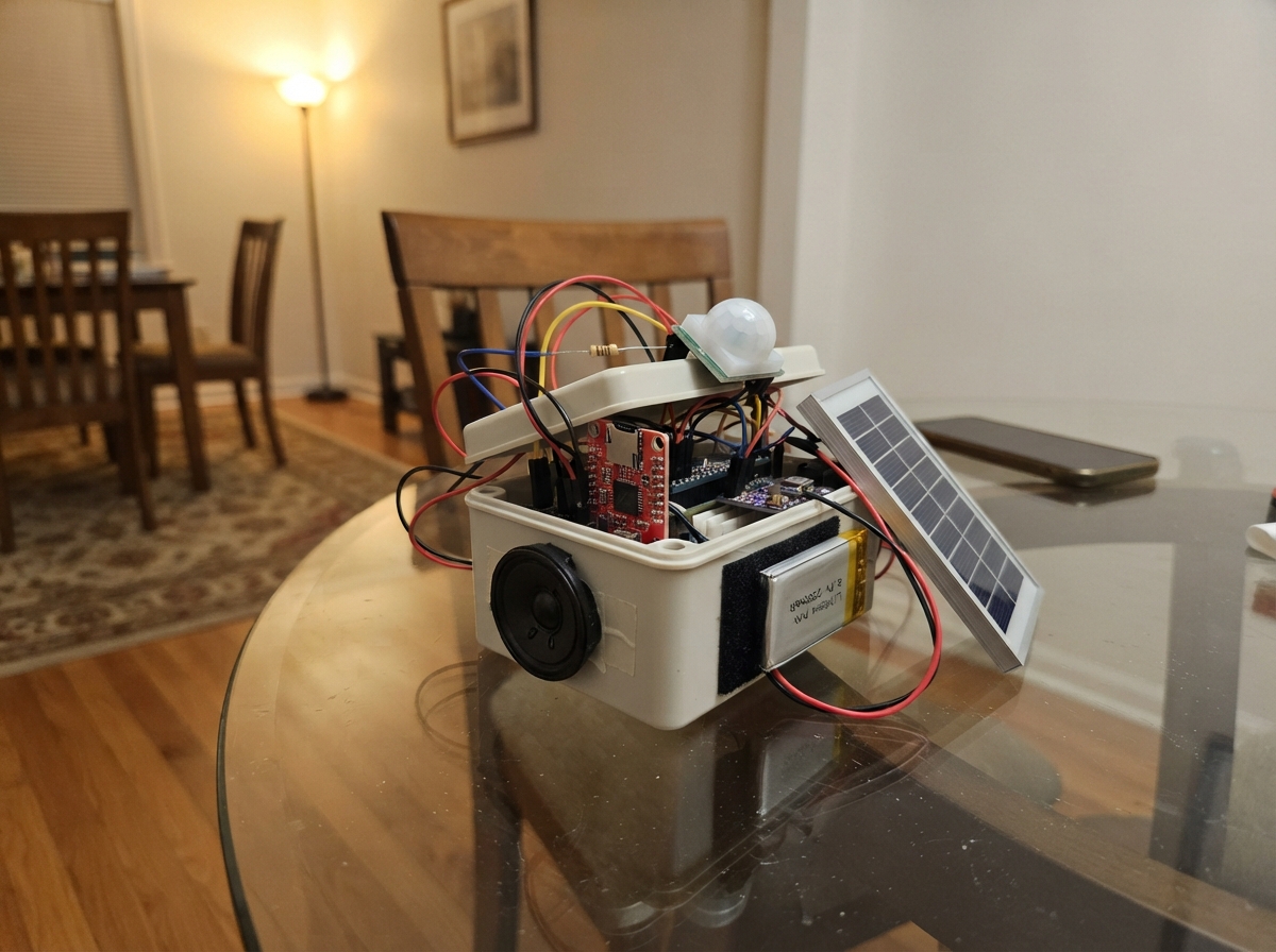
The IoT Crop Guardian Drone is a solar-powered wildlife deterrent system built around an ESP32 microcontroller that detects motion with a PIR sensor and responds with audio alerts and visual flashes. When motion is detected in crop fields, the system plays prerecorded deterrent sounds through a speaker and triggers the onboard LED flash to scare away animals, while capturing images for remote monitoring via a connected Raspberry Pi.
This guide provides everything needed to assemble and deploy a crop protection node: a complete parts list, wiring diagram for integrating the motion sensor, audio module, and solar charging system, step-by-step assembly instructions, and ready-to-use ESP32 firmware that handles motion detection, sound playback, image capture, and wireless communication. Builders will learn how to configure the system for their field location and customize deterrent responses.
Wiring diagram
Gather all the parts
Assemble it in 7 steps
1. Prepare the sound card
On a computer, format sound_card_1 as FAT32. Make a folder named mp3 and copy three different deterrent sounds into it as 0001.mp3, 0002.mp3, and 0003.mp3. Slide the card fully into the side socket on dfplayer_1 with the metal contacts facing the socket contacts.
- Use short recordings such as barking, an alarm, and a predator call so the sounds vary between events.
- Do not remove the card while dfplayer_1 has power; removing it while powered can corrupt the sound files.
2. Connect the sound player and speaker
Connect dfplayer_1 VCC to the 5V output of solar_charger_1 (power) and dfplayer_1 GND to the common GND line (ground). Connect dfplayer_1 SPK1 to speaker_1 POS and dfplayer_1 SPK2 to speaker_1 NEG (sound). Connect dfplayer_1 TX to GPIO3 on the ESP32-CAM (data) and dfplayer_1 RX to GPIO1 on the ESP32-CAM (data).
- Mount the horn speaker facing the crop edge, and keep the speaker and DFPlayer inside a splash-protected box with a downward-facing sound opening.
- Never connect either speaker wire to GND; SPK1 and SPK2 are the two amplified speaker wires, and grounding one can damage dfplayer_1.
3. Wire the motion sensor safely
Connect pir_1 VCC to the 5V output of solar_charger_1 (power) and pir_1 GND to the common GND line (ground). Connect pir_1 OUT to one leg of pir_divider_top_1, join its other leg to one leg of pir_divider_bottom_1, then connect that joined point to GPIO13 on the ESP32-CAM (motion signal). Connect the remaining leg of pir_divider_bottom_1 to GND (ground).
- The 10 kΩ resistor is pir_divider_top_1 and the 20 kΩ resistor is pir_divider_bottom_1. Keep the two joined resistor legs and the GPIO13 wire in the same breadboard row or solder junction.
- Do not connect the PIR OUT pin directly to GPIO13: some PIR boards use a 5 V motion signal, which can damage the 3.3 V ESP32-CAM input.
4. Build the solar power chain
Connect solar_panel_1 V+ to solar_charger_1 VIN (solar charging input) and solar_panel_1 GND to solar_charger_1 GND (solar return). Plug battery_1 into the BAT connector on solar_charger_1. Connect solar_charger_1 5V to the ESP32-CAM 5V pin, the PIR VCC, and the DFPlayer VCC (power). Join every ground wire to solar_charger_1 GND (ground).
- Place the solar panel where it has daylight, and place the battery and charger inside the dry enclosure.
- Keep V+ and GND from the solar panel separate; swapped or shorted solar wires can damage the charger. Use only the protected single-cell battery listed here.
5. Mount the camera node
Aim the ESP32-CAM lens toward the approach path and keep its built-in white flash LED visible through a clear window; it is the flashing light deterrent. Put the PIR dome below or beside the lens, pointing at the same area. Keep the camera lens, PIR dome, and speaker opening outside the sealed electronics space, while keeping the circuit boards dry.
- Avoid aiming the PIR at moving branches, reflective metal, or a road, because these can cause unwanted alarms.
- Do not seal the PIR dome behind thick plastic or the sensor will not detect body heat and movement reliably.
6. Load the ESP32-CAM safely
Before using the Deploy button, unplug the two serial wires between dfplayer_1 and GPIO1/GPIO3 on the ESP32-CAM. After flashing, reconnect dfplayer_1 TX to GPIO3 and dfplayer_1 RX to GPIO1, then power-cycle the node.
- Those two pins are shared with the ESP32-CAM programming connection, so temporarily unplugging the MP3 player prevents it from interfering with the firmware upload.
- Do not swap the two serial wires: TX on dfplayer_1 goes to GPIO3, and RX on dfplayer_1 goes to GPIO1.
7. Connect the Raspberry Pi link
Set the Raspberry Pi Wi-Fi connection to join the CropGuard-Node network using password CropGuard1, then give its Wi-Fi connection the local address 192.168.4.2. Run its photo receiver so it listens at port 8080 on the path /cropguard/photo; the ESP32-CAM sends each photo there when the PIR finds motion.
- On a phone or computer connected to CropGuard-Node, open 192.168.4.1/status to see the node state, 192.168.4.1/sound to start the sound and light, or 192.168.4.1/capture to request a photo.
- The Raspberry Pi must have a photo receiver running before animal detection can reach the ML and notification phase; without it, the local sound and flashing light still operate.
Review all connections
1. Connections between "solar_panel_1" and "ESP32"
2. Connections between "battery_1" and "ESP32"
3. Connections between "solar_charger_1" and "ESP32"
4. Connections between "pir_1" and "ESP32"
5. Connections between "pir_divider_top_1" and "ESP32"
6. Connections between "pir_divider_bottom_1" and "ESP32"
7. Connections between "dfplayer_1" and "ESP32"
Deploy the firmware
#include <Arduino.h>
#include "esp_camera.h"
#include <WiFi.h>
#include <WebServer.h>
#include <HTTPClient.h>

// AI Thinker ESP32-CAM camera wiring is fixed on the board.
#define PWDN_GPIO_NUM     32
#define RESET_GPIO_NUM    -1
#define XCLK_GPIO_NUM      0
#define SIOD_GPIO_NUM     26
#define SIOC_GPIO_NUM     27
#define Y9_GPIO_NUM       35
#define Y8_GPIO_NUM       34
#define Y7_GPIO_NUM       39
#define Y6_GPIO_NUM       36
#define Y5_GPIO_NUM       21
#define Y4_GPIO_NUM       19
#define Y3_GPIO_NUM       18
#define Y2_GPIO_NUM        5
#define VSYNC_GPIO_NUM    25
#define HREF_GPIO_NUM     23
#define PCLK_GPIO_NUM     22

constexpr int PIR_PIN = 13;
constexpr int DFPLAYER_RX_PIN = 3;  // DFPlayer TX -> ESP32-CAM RX0
constexpr int DFPLAYER_TX_PIN = 1;  // DFPlayer RX -> ESP32-CAM TX0
constexpr int FLASH_LED_PIN = 4;    // white flash LED already fitted to the ESP32-CAM

const char *AP_SSID = "CropGuard-Node";
const char *AP_PASSWORD = "CropGuard1";
const char *PI_UPLOAD_URL = "http://192.168.4.2:8080/cropguard/photo";
const char *NODE_ID = "field-node-01";
const char *NODE_LOCATION = "replace-with-field-GPS-location";

WebServer server(80);
HardwareSerial &dfSerial = Serial;
bool alarmActive = false;
bool motionArmed = true;
uint32_t alarmStartedAt = 0;
uint32_t lastFlashAt = 0;
uint32_t eventCount = 0;
const uint32_t ALARM_DURATION_MS = 60000;
const uint32_t FLASH_INTERVAL_MS = 250;

uint16_t dfChecksum(uint8_t command, uint16_t parameter) {
  return 0U - (0xFF + 0x06 + command + (parameter >> 8) + (parameter & 0xFF));
}

void dfCommand(uint8_t command, uint16_t parameter) {
  const uint16_t check = dfChecksum(command, parameter);
  const uint8_t packet[] = {0x7E, 0xFF, 0x06, command, 0x00,
    static_cast<uint8_t>(parameter >> 8), static_cast<uint8_t>(parameter),
    static_cast<uint8_t>(check >> 8), static_cast<uint8_t>(check), 0xEF};
  dfSerial.write(packet, sizeof(packet));
}

void playRandomDeterrentSound() {
  dfCommand(0x03, random(1, 4)); // /mp3/0001.mp3 to /mp3/0003.mp3
}

bool captureAndUpload() {
  camera_fb_t *frame = esp_camera_fb_get();
  if (frame == nullptr) return false;
  HTTPClient http;
  http.setConnectTimeout(1500);
  http.setTimeout(3500);
  http.begin(PI_UPLOAD_URL);
  http.addHeader("Content-Type", "image/jpeg");
  http.addHeader("X-CropGuard-Node", NODE_ID);
  http.addHeader("X-CropGuard-Location", NODE_LOCATION);
  http.addHeader("X-CropGuard-Event", String(eventCount));
  const int result = http.POST(frame->buf, frame->len);
  http.end();
  esp_camera_fb_return(frame);
  return result >= 200 && result < 300;
}

void startAlarm() {
  if (alarmActive) return;
  eventCount++;
  captureAndUpload();
  playRandomDeterrentSound();
  alarmActive = true;
  alarmStartedAt = millis();
  lastFlashAt = 0;
  digitalWrite(FLASH_LED_PIN, HIGH);
}

void handleStatus() {
  String json = "{\"node\":\"" + String(NODE_ID) + "\",\"alarm\":";
  json += alarmActive ? "true" : "false";
  json += ",\"events\":" + String(eventCount) + "}";
  server.send(200, "application/json", json);
}

void handleSound() {
  startAlarm();
  server.send(200, "text/plain", "Level 1 sound and light started");
}

void handleCapture() {
  eventCount++;
  const bool uploaded = captureAndUpload();
  server.send(uploaded ? 200 : 503, "text/plain", uploaded ? "Photo sent to Raspberry Pi" : "Photo captured but Raspberry Pi did not accept it");
}

bool initCamera() {
  camera_config_t config = {};
  config.ledc_channel = LEDC_CHANNEL_0;
  config.ledc_timer = LEDC_TIMER_0;
  config.pin_d0 = Y2_GPIO_NUM; config.pin_d1 = Y3_GPIO_NUM;
  config.pin_d2 = Y4_GPIO_NUM; config.pin_d3 = Y5_GPIO_NUM;
  config.pin_d4 = Y6_GPIO_NUM; config.pin_d5 = Y7_GPIO_NUM;
  config.pin_d6 = Y8_GPIO_NUM; config.pin_d7 = Y9_GPIO_NUM;
  config.pin_xclk = XCLK_GPIO_NUM; config.pin_pclk = PCLK_GPIO_NUM;
  config.pin_vsync = VSYNC_GPIO_NUM; config.pin_href = HREF_GPIO_NUM;
  config.pin_sscb_sda = SIOD_GPIO_NUM; config.pin_sscb_scl = SIOC_GPIO_NUM;
  config.pin_pwdn = PWDN_GPIO_NUM; config.pin_reset = RESET_GPIO_NUM;
  config.xclk_freq_hz = 20000000;
  config.pixel_format = PIXFORMAT_JPEG;
  config.frame_size = FRAMESIZE_VGA;
  config.jpeg_quality = 12;
  config.fb_count = psramFound() ? 2 : 1;
  return esp_camera_init(&config) == ESP_OK;
}

void setup() {
  pinMode(PIR_PIN, INPUT);
  pinMode(FLASH_LED_PIN, OUTPUT);
  digitalWrite(FLASH_LED_PIN, LOW);
  // UART0 is shared with programming: unplug DFPlayer TX/RX before flashing.
  dfSerial.begin(9600, SERIAL_8N1, DFPLAYER_RX_PIN, DFPLAYER_TX_PIN);
  delay(1200);
  dfCommand(0x3F, 0);
  delay(500);
  dfCommand(0x06, 25);
  initCamera();
  randomSeed(micros());
  WiFi.mode(WIFI_AP);
  WiFi.softAP(AP_SSID, AP_PASSWORD);
  server.on("/status", HTTP_GET, handleStatus);
  server.on("/sound", HTTP_GET, handleSound);
  server.on("/capture", HTTP_GET, handleCapture);
  server.begin();
}

void loop() {
  server.handleClient();
  const bool motionNow = digitalRead(PIR_PIN) == HIGH;
  if (!motionNow) motionArmed = true;
  if (motionNow && motionArmed && !alarmActive) {
    motionArmed = false;
    startAlarm();
  }
  if (alarmActive) {
    const uint32_t now = millis();
    if (now - lastFlashAt >= FLASH_INTERVAL_MS) {
      lastFlashAt = now;
      digitalWrite(FLASH_LED_PIN, !digitalRead(FLASH_LED_PIN));
    }
    if (now - alarmStartedAt >= ALARM_DURATION_MS) {
      alarmActive = false;
      digitalWrite(FLASH_LED_PIN, LOW);
      dfCommand(0x16, 0);
    }
  }
  delay(10);
}
Remix this project
Make it yours in one click
Open a full copy of this project in your own Schematik workspace, diagram, code, parts, and assembly steps included. Swap the sensor, add features, or redesign the whole thing with AI. The author's original stays untouched.