Community project
Line-Following Delivery Cart
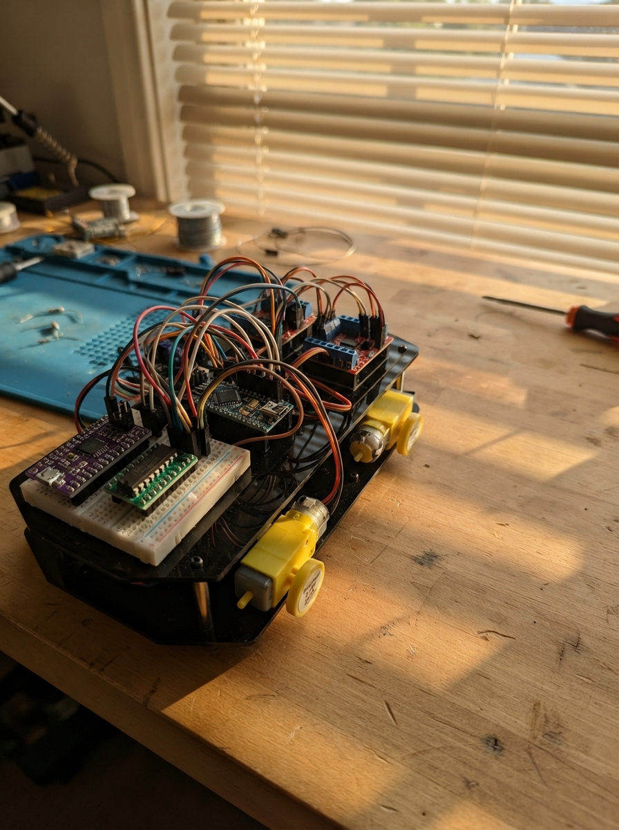
This line-following delivery cart is a four-wheel autonomous robot built around an ESP32 microcontroller that navigates marked paths while avoiding obstacles. The cart uses dual TB6612FNG motor drivers to control four independent Faulhaber DC motors, an MCP23017 I2C expander for motor direction control, and an 8-channel multiplexer to manage multiple ultrasonic distance sensors. Power comes from a 2S LiPo battery with a 5V buck converter for the logic circuits.
This guide provides a complete wiring diagram, detailed parts list, and step-by-step assembly instructions for building the chassis, mounting motors and sensors, and integrating the power distribution system. The included ESP32 firmware implements line-following with proportional steering correction, obstacle detection with eight ultrasonic sensors, and automatic stopping when objects are too close. Builders will learn motor control techniques, I2C peripheral expansion, analog multiplexing, and sensor fusion for autonomous navigation.
Wiring diagram

Gather all the parts
Assemble it in 6 steps
1. Monta el chasis y la canastilla
Fija los cuatro motores en las cuatro esquinas del chasis. Atornilla la canastilla baja y centrada entre los ejes; deja los ocho sensores de distancia mirando hacia fuera, con el sensor 1 en el frente. Coloca los dos sensores de línea debajo del borde delantero, separados a ambos lados de la línea.
- La canastilla debe quedar lo más baja posible; una carga alta hace más fácil que el carro vuelque.
- Deja aproximadamente 8 mm entre cada TCRT5000 y el suelo para que pueda distinguir la cinta negra.
- No añadas carga a la canastilla hasta probar el carro en el suelo: una carga suelta puede caer sobre las ruedas.
2. Conecta los motores a los dos controladores
Conecta motor_fl a A01 y A02, y motor_fr a B01 y B02 de driver_front. Conecta motor_rl a A01 y A02, y motor_rr a B01 y B02 de driver_rear. Si una rueda gira al revés en la primera prueba, intercambia solamente los dos cables de ese motor.
- Usa cables gruesos y cortos para los motores; los cables finos se calientan y hacen que el carro pierda fuerza.
- No conectes los cables de los motores a ningún pin del ESP32: pueden dañarlo.
3. Arma la alimentación protegida
Conecta battery BAT+ al pin IN de fuse_main y fuse_main OUT a buck_5v VIN+. Conecta battery BAT- a buck_5v VIN-. Ajusta primero el buck_5v a 5,0 V con un multímetro. Lleva VOUT+ a VM de ambos controladores, a VCC de los ocho HC-SR04 y a VCC del multiplexor; lleva VOUT- a todas las conexiones GND. Lleva 3V3 del ESP32 a VCC de ambos controladores, VDD del expansor, VIN del MPU-6050 y VCC de ambos TCRT5000.
- Todas las tierras GND deben estar unidas: así las señales tienen la misma referencia.
- El fusible va cerca del cable positivo de la batería.
- Ajusta el regulador antes de conectar el ESP32 o los sensores; más de 5 V puede dañarlos.
- No uses los controladores TB6612 si un motor Faulhaber supera 1 A al bloquearse; el controlador se puede quemar.
4. Conecta el ESP32, los controladores y el expansor
Conecta GPIO21 a SDA y GPIO22 a SCL de motor_io y del MPU-6050. Conecta RESET de motor_io a 3V3. Conecta GPA0 y GPA1 a AIN1 y AIN2 de los dos controladores; conecta GPA2 y GPA3 a BIN1 y BIN2 de los dos controladores. Conecta STBY de ambos controladores a 3V3. Conecta PWMA de los controladores delantero y trasero a GPIO16 y GPIO18; conecta sus PWMB a GPIO17 y GPIO19.
- El expansor manda las órdenes de sentido a ambos lados del carro; las cuatro conexiones PWM regulan la velocidad de cada rueda.
- No intercambies VCC de 3V3 con VM de 5V en los TB6612: VM alimenta motores y VCC alimenta las señales.
5. Conecta los lectores de línea y los sensores de distancia
Conecta AO de line_left a GPIO35 y AO de line_right a GPIO36; conecta sus VCC a 3V3 y sus GND a GND. Conecta S0, S1 y S2 de range_mux a GPIO25, GPIO26 y GPIO27, y EN a GND. Conecta COM del multiplexor al divisor: COM a P1 de echo_r_top, P2 de echo_r_top a P1 de echo_r_bottom y también a GPIO34, y P2 de echo_r_bottom a GND. Conecta ECHO de sonar_1 a X0, sonar_2 a X1 y así hasta sonar_8 a X7. Conecta TRIG de sonar_1 a GPA4, sonar_2 a GPA5, sonar_3 a GPA6, sonar_4 a GPA7, sonar_5 a GPB0, sonar_6 a GPB1, sonar_7 a GPB2 y sonar_8 a GPB3.
- El par de resistencias baja la señal ECHO de 5 V a un nivel seguro para el ESP32 de 3,3 V.
- Los ultrasonidos se activan de uno en uno para evitar que uno escuche el eco de otro.
- No conectes ECHO directamente a GPIO34: la señal de 5 V puede dañar el ESP32.
6. Haz la primera prueba sin carga
Eleva el chasis para que las ruedas no toquen la mesa. Conecta la batería y después el ESP32 por USB. Comprueba que no hay cables calientes ni olor a plástico. Después de desplegar el programa, pon el carro sobre una línea oscura y ajusta los pequeños tornillos de los TCRT5000 hasta que detecten claramente la línea.
- Prueba primero sin productos en la canastilla y a poca velocidad; después añade peso poco a poco.
- Mantén dedos, ropa y cables lejos de las ruedas cuando reciban energía.
Review all connections
1. Connections between "battery" and "ESP32"
2. Connections between "buck_5v" and "ESP32"
3. Connections between "driver_front" and "ESP32"
4. Connections between "driver_rear" and "ESP32"
5. Connections between "motor_io" and "ESP32"
6. Connections between "range_mux" and "ESP32"
7. Connections between "echo_r_top" and "ESP32"
8. Connections between "echo_r_bottom" and "ESP32"
9. Connections between "imu" and "ESP32"
10. Connections between "line_left" and "ESP32"
11. Connections between "line_right" and "ESP32"
12. Connections between "sonar_1" and "ESP32"
13. Connections between "sonar_2" and "ESP32"
14. Connections between "sonar_3" and "ESP32"
15. Connections between "sonar_4" and "ESP32"
16. Connections between "sonar_5" and "ESP32"
17. Connections between "sonar_6" and "ESP32"
18. Connections between "sonar_7" and "ESP32"
19. Connections between "sonar_8" and "ESP32"
20. Connections between "fuse_main" and "ESP32"
Deploy the firmware
#include <Arduino.h>
#include <Wire.h>
#include <Adafruit_MCP23X17.h>

constexpr int PWM_FL_PIN = 16;
constexpr int PWM_FR_PIN = 17;
constexpr int PWM_RL_PIN = 18;
constexpr int PWM_RR_PIN = 19;
constexpr int I2C_SDA_PIN = 21;
constexpr int I2C_SCL_PIN = 22;
constexpr int MUX_S0_PIN = 25;
constexpr int MUX_S1_PIN = 26;
constexpr int MUX_S2_PIN = 27;
constexpr int ECHO_PIN = 34;
constexpr int LINE_LEFT_PIN = 35;
constexpr int LINE_RIGHT_PIN = 36;

constexpr uint8_t MCP_ADDRESS = 0x20;
constexpr uint8_t MPU_ADDRESS = 0x68;
constexpr uint8_t DIR_LEFT_1 = 0;
constexpr uint8_t DIR_LEFT_2 = 1;
constexpr uint8_t DIR_RIGHT_1 = 2;
constexpr uint8_t DIR_RIGHT_2 = 3;
constexpr uint8_t TRIGGER_BASE = 4;
constexpr int LINE_THRESHOLD = 2000;
constexpr bool LINE_DARK_HIGH = true;
constexpr uint8_t CRUISE_SPEED = 145;
constexpr uint8_t TURN_SPEED = 85;
constexpr uint16_t STOP_DISTANCE_CM = 22;
constexpr int16_t TILT_LIMIT_RAW = 8000;
constexpr uint32_t SONAR_INTERVAL_MS = 60;

Adafruit_MCP23X17 mcp;
bool mpuPresent = false;
uint16_t distancesCm[8] = {0};
uint8_t nextSonar = 0;
uint32_t lastSonarMs = 0;

void setMotorPwm(uint8_t leftSpeed, uint8_t rightSpeed) {
  ledcWrite(0, leftSpeed);
  ledcWrite(1, rightSpeed);
  ledcWrite(2, leftSpeed);
  ledcWrite(3, rightSpeed);
}

void setDirection(bool forward) {
  mcp.digitalWrite(DIR_LEFT_1, forward ? HIGH : LOW);
  mcp.digitalWrite(DIR_LEFT_2, forward ? LOW : HIGH);
  mcp.digitalWrite(DIR_RIGHT_1, forward ? HIGH : LOW);
  mcp.digitalWrite(DIR_RIGHT_2, forward ? LOW : HIGH);
}

void stopCar() {
  setMotorPwm(0, 0);
}

void selectEcho(uint8_t channel) {
  digitalWrite(MUX_S0_PIN, channel & 0x01);
  digitalWrite(MUX_S1_PIN, (channel >> 1) & 0x01);
  digitalWrite(MUX_S2_PIN, (channel >> 2) & 0x01);
  delayMicroseconds(5);
}

uint16_t readSonarCm(uint8_t channel) {
  selectEcho(channel);
  uint8_t triggerPin = TRIGGER_BASE + channel;
  mcp.digitalWrite(triggerPin, LOW);
  delayMicroseconds(4);
  mcp.digitalWrite(triggerPin, HIGH);
  delayMicroseconds(15);
  mcp.digitalWrite(triggerPin, LOW);
  unsigned long pulse = pulseIn(ECHO_PIN, HIGH, 24000);
  if (pulse == 0) return 0;
  return static_cast<uint16_t>(pulse / 58UL);
}

bool isLine(int raw) {
  return LINE_DARK_HIGH ? raw >= LINE_THRESHOLD : raw < LINE_THRESHOLD;
}

bool isTilted() {
  if (!mpuPresent) return false;
  Wire.beginTransmission(MPU_ADDRESS);
  Wire.write(0x3B);
  if (Wire.endTransmission(false) != 0) return false;
  if (Wire.requestFrom(MPU_ADDRESS, static_cast<uint8_t>(6)) != 6) return false;
  int16_t ax = (Wire.read() << 8) | Wire.read();
  int16_t ay = (Wire.read() << 8) | Wire.read();
  Wire.read();
  Wire.read();
  return abs(ax) > TILT_LIMIT_RAW || abs(ay) > TILT_LIMIT_RAW;
}

void followLine() {
  bool leftOnLine = isLine(analogRead(LINE_LEFT_PIN));
  bool rightOnLine = isLine(analogRead(LINE_RIGHT_PIN));
  setDirection(true);
  if (leftOnLine && !rightOnLine) {
    setMotorPwm(TURN_SPEED, CRUISE_SPEED);
  } else if (!leftOnLine && rightOnLine) {
    setMotorPwm(CRUISE_SPEED, TURN_SPEED);
  } else if (leftOnLine && rightOnLine) {
    setMotorPwm(CRUISE_SPEED, CRUISE_SPEED);
  } else {
    setMotorPwm(0, 0);
  }
}

void setup() {
  Serial.begin(115200);
  Wire.begin(I2C_SDA_PIN, I2C_SCL_PIN);
  analogReadResolution(12);
  pinMode(MUX_S0_PIN, OUTPUT);
  pinMode(MUX_S1_PIN, OUTPUT);
  pinMode(MUX_S2_PIN, OUTPUT);
  pinMode(ECHO_PIN, INPUT);
  pinMode(LINE_LEFT_PIN, INPUT);
  pinMode(LINE_RIGHT_PIN, INPUT);
  ledcSetup(0, 20000, 8);
  ledcSetup(1, 20000, 8);
  ledcSetup(2, 20000, 8);
  ledcSetup(3, 20000, 8);
  ledcAttachPin(PWM_FL_PIN, 0);
  ledcAttachPin(PWM_FR_PIN, 1);
  ledcAttachPin(PWM_RL_PIN, 2);
  ledcAttachPin(PWM_RR_PIN, 3);
  if (!mcp.begin_I2C(MCP_ADDRESS, &Wire)) {
    Serial.println("MCP23017 not found; motors remain stopped.");
    while (true) delay(1000);
  }
  for (uint8_t pin = 0; pin < 12; pin++) {
    mcp.pinMode(pin, OUTPUT);
    mcp.digitalWrite(pin, LOW);
  }
  Wire.beginTransmission(MPU_ADDRESS);
  mpuPresent = (Wire.endTransmission() == 0);
  if (mpuPresent) {
    Wire.beginTransmission(MPU_ADDRESS);
    Wire.write(0x6B);
    Wire.write(0x00);
    Wire.endTransmission();
  }
  stopCar();
}

void loop() {
  uint32_t now = millis();
  if (now - lastSonarMs >= SONAR_INTERVAL_MS) {
    distancesCm[nextSonar] = readSonarCm(nextSonar);
    nextSonar = (nextSonar + 1) % 8;
    lastSonarMs = now;
  }
  bool frontBlocked = distancesCm[0] > 0 && distancesCm[0] <= STOP_DISTANCE_CM;
  if (frontBlocked || isTilted()) {
    stopCar();
  } else {
    followLine();
  }
}
Remix this project
Make it yours in one click
Open a full copy of this project in your own Schematik workspace — diagram, code, parts, and assembly steps included. Swap the sensor, add features, or redesign the whole thing with AI. The author's original stays untouched.