Community project
M5Stick S3 Display Demo
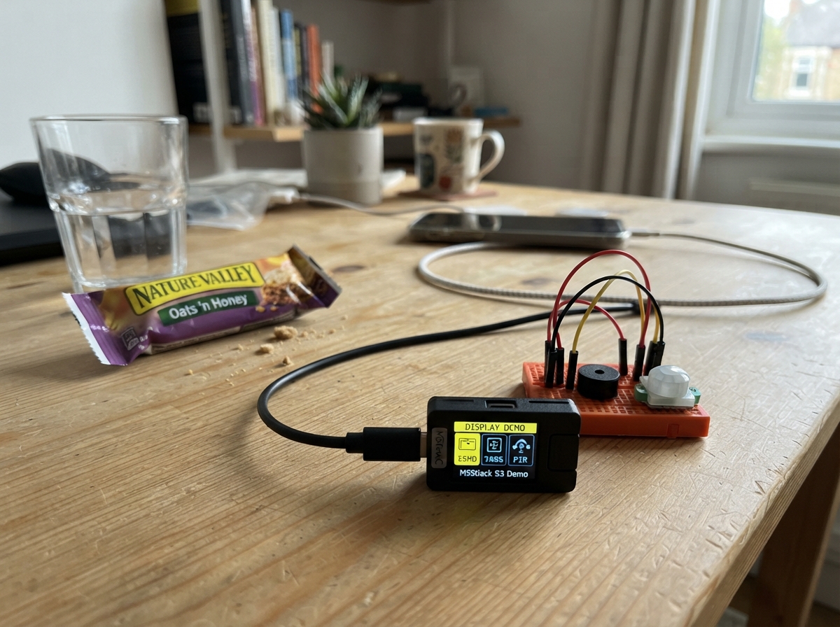
This project demonstrates how to display custom images and graphics on the M5Stick S3's built-in screen. The guide covers everything needed to load and render bitmap images, configure the display orientation, and manage screen updates efficiently on an ESP32-based device.
Followers will receive a complete parts list, wiring instructions for the USB-C connection, a ready-to-use firmware sketch, and step-by-step assembly directions to get images displaying on the screen within minutes.
Wiring diagram
Assemble it in 2 steps
1. Use the built-in screen
No breadboard wires or extra parts are needed. The image is stored inside the StickS3 program and is drawn on its own front screen.
- Leave the small screen uncovered so you can see the full image.
- Do not connect power to any exposed pins for this project; the StickS3 is powered safely from its USB-C port.
2. Connect the USB-C cable
Plug a USB-C data cable into the StickS3 and your computer. This powers the device and lets Schematik send the screen program to it.
- If the screen stays off, try a different USB-C cable because some cables provide power only.
Deploy the firmware
#include <M5Unified.h>
#include "breadboard_image.h"

void setup() {
  auto config = M5.config();
  M5.begin(config);

  M5.Display.setRotation(0);
  M5.Display.startWrite();
  M5.Display.fillScreen(TFT_BLACK);
  M5.Display.draw16bitRGBBitmap(0, 0, BREADBOARD_IMAGE_DATA,
                                BREADBOARD_IMAGE_WIDTH,
                                BREADBOARD_IMAGE_HEIGHT);
  M5.Display.endWrite();
}

void loop() {
  M5.update();
  delay(20);
}
Remix this project
Make it yours in one click
Open a full copy of this project in your own Schematik workspace — diagram, code, parts, and assembly steps included. Swap the sensor, add features, or redesign the whole thing with AI. The author's original stays untouched.