Community project
Live Bus Arrival Display
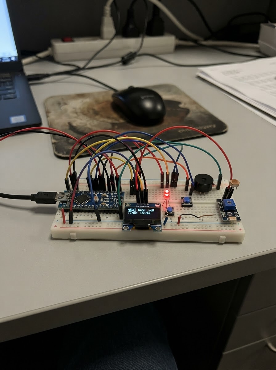
This project builds a real-time bus arrival display that connects to Wi-Fi to fetch and show upcoming bus schedules on an OLED screen. The ESP32 microcontroller manages the display, status LEDs, and user controls to create a practical transit information station for home or office use.
The guide provides a complete wiring diagram, parts list, and step-by-step assembly instructions for connecting the SSD1306 OLED display, three status LEDs with resistors, a push button for navigation, a buzzer for alerts, and an LDR light sensor for automatic brightness adjustment. Firmware is included to handle Wi-Fi connectivity, bus data updates, and adaptive display modes based on ambient light conditions.
Wiring diagram

Gather all the parts
Assemble it in 6 steps
1. Separe as peças e desligue a placa
Deixe a Adafruit ESP32 Feather desconectada do cabo USB enquanto monta. Use uma protoboard e fios jumper; todos os módulos precisam compartilhar o mesmo GND para os sinais funcionarem.
- Coloque a Feather atravessando o vão central da protoboard para acessar os dois lados.
- Use fios pretos para GND, vermelhos para 3V3 e outras cores para sinais.
- Não conecte o OLED ou o módulo de luz em 5 V: estes itens foram planejados para 3,3 V e a tensão errada pode danificá-los.
2. Ligue o display OLED
No OLED de quatro pinos, ligue VCC ao pino 3V3 da Feather (alimentação), GND ao GND (retorno de energia), SDA ao GPIO23 (dados do display) e SCL ao GPIO22 (relógio do display).
- Confira as letras impressas na placa do OLED; alguns módulos mostram os pinos em ordem diferente.
- O endereço usado pelo programa é 0x3C, comum em OLEDs SSD1306 de 128×64.
- Não troque VCC e GND — energia invertida pode danificar o display.
3. Monte os três LEDs com resistores
Para cada LED, use um resistor de 220 Ω em série: GPIO25 vai ao resistor verde, e a outra ponta do resistor vai ao terminal longo do LED verde; o terminal curto vai ao GND. Repita com GPIO26, resistor amarelo e LED amarelo; depois GPIO27, resistor vermelho e LED vermelho. Os resistores limitam a corrente para os LEDs não queimarem.
- O terminal longo do LED é o positivo; o lado achatado do corpo indica o terminal curto, que vai ao GND.
- Cada LED precisa do seu próprio resistor de 220 Ω.
- Nunca ligue um LED diretamente a um GPIO: sem resistor ele pode queimar o LED ou sobrecarregar a placa.
4. Ligue o botão e o buzzer
Coloque o botão atravessando o vão central da protoboard. Ligue um lado do botão ao GPIO33 (sinal) e o lado oposto ao GND (retorno); o programa já mantém esse pino em estado estável. Ligue o terminal positivo ou marcado do buzzer piezo ao GPIO18 (som) e o outro terminal ao GND (retorno).
- Se o botão não responder, gire-o 90 graus: os dois terminais de cada lado do botão geralmente já estão unidos internamente.
- No buzzer, procure o sinal + para identificar o terminal que vai ao GPIO18.
- Não conecte o buzzer a 5 V; o circuito foi definido para sinais de 3,3 V da Feather.
5. Ligue o sensor de luz
No módulo de luminosidade, ligue VCC ao 3V3 da Feather (alimentação), GND ao GND (retorno) e AO ao GPIO34 (leitura da luz). Deixe o LDR, a pequena peça redonda com trilhas visíveis, exposto à luz do ambiente.
- O pino AO é a saída analógica; não use DO para este projeto.
- Se à noite a tela ficar mais clara em vez de mais fraca, ajuste o pequeno trimpot do módulo ou inverta a comparação de brilho no código.
- Não ligue AO a 5 V: GPIO34 aceita somente níveis de até 3,3 V e tensão maior pode danificar a Feather.
6. Faça o teste físico inicial
Revise se cada GND chega ao GND da Feather e se não há fios soltos. Conecte a Feather ao computador por USB. Depois de configurar o nome e a senha da sua rede nas duas constantes do programa, use o botão Deploy do Schematik para compilar e gravar. A tela deve mostrar três ônibus; um toque no botão destaca a próxima linha, e os LEDs acompanham o tempo da linha destacada.
- Com os dados simulados, a cada 30 segundos os tempos alternam entre 3/9/18, 2/8/16 e 1/6/14 minutos.
- Ao selecionar uma linha com menos de 2 minutos, o buzzer toca uma vez.
- Cubra o LDR com a mão: o OLED deve reduzir o brilho.
- Se a tela mostrar SEM INTERNET, confira primeiro o nome e a senha da rede; o circuito continua seguro e tenta reconectar automaticamente.
Review all connections
1. Connections between "oled" and "ESP32"
2. Connections between "resistor_verde" and "ESP32"
3. Connections between "led_verde" and "ESP32"
4. Connections between "resistor_amarelo" and "ESP32"
5. Connections between "led_amarelo" and "ESP32"
6. Connections between "resistor_vermelho" and "ESP32"
7. Connections between "led_vermelho" and "ESP32"
8. Connections between "botao" and "ESP32"
9. Connections between "buzzer" and "ESP32"
10. Connections between "sensor_luz" and "ESP32"
Deploy the firmware
#include <Arduino.h>
#include <WiFi.h>
#include <Wire.h>
#include <Adafruit_GFX.h>
#include <Adafruit_SSD1306.h>

// Troque estas duas strings pelos dados da sua rede Wi-Fi antes de usar.

struct BusInfo {
  const char *line;
  const char *destination;
  int minutes;
};


// Forward declarations
bool wifiIsConnected();
void connectWiFi();
void loadSimulatedBusData();
void setStatusLEDs(int minutes);
void setDisplayBrightnessIfNeeded();
void drawBusScreen();
void drawOfflineScreen();
void updateArrivalAlert();
void readButton();
void refreshVisibleState();

const char *WIFI_SSID = "SEU_WIFI";
const char *WIFI_PASSWORD = "SUA_SENHA";

const int OLED_SDA = 23;
const int OLED_SCL = 22;
const int LED_GREEN_PIN = 25;
const int LED_YELLOW_PIN = 26;
const int LED_RED_PIN = 27;
const int BUTTON_PIN = 33;
const int BUZZER_PIN = 18;
const int LDR_PIN = 34;

const unsigned long UPDATE_INTERVAL_MS = 30000UL;
const unsigned long BUTTON_DEBOUNCE_MS = 250UL;
const unsigned long RECONNECT_INTERVAL_MS = 10000UL;
const int NIGHT_LIGHT_THRESHOLD = 1400;
const uint8_t OLED_BRIGHTNESS_DAY = 0xCF;
const uint8_t OLED_BRIGHTNESS_NIGHT = 0x20;


BusInfo buses[3] = {
  {"431", "Centro", 3},
  {"702", "Terminal Norte", 9},
  {"815", "Rodoviaria", 18}
};

Adafruit_SSD1306 display(128, 64, &Wire, -1);

int selectedBus = 0;
unsigned long lastDataUpdateMs = 0;
unsigned long lastButtonMs = 0;
unsigned long lastReconnectMs = 0;
bool lastButtonState = HIGH;
bool alertAlreadyPlayed = false;
bool screenNeedsRedraw = true;
bool lastWifiState = false;
int lastBrightnessMode = -1;

bool wifiIsConnected() {
  return WiFi.status() == WL_CONNECTED;
}

void connectWiFi() {
  WiFi.mode(WIFI_STA);
  WiFi.begin(WIFI_SSID, WIFI_PASSWORD);
}

void loadSimulatedBusData() {
  // Ponto de troca para uma API real: após ler HTTP/JSON, atualize
  // buses[i].line, buses[i].destination e buses[i].minutes nesta função.
  static int cycle = 0;
  const int sampleMinutes[3][3] = {
    {3, 9, 18},
    {2, 8, 16},
    {1, 6, 14}
  };

  for (int i = 0; i < 3; i++) {
    buses[i].minutes = sampleMinutes[cycle][i];
  }
  cycle = (cycle + 1) % 3;
}

void setStatusLEDs(int minutes) {
  digitalWrite(LED_GREEN_PIN, minutes <= 5 ? HIGH : LOW);
  digitalWrite(LED_YELLOW_PIN, (minutes >= 6 && minutes <= 15) ? HIGH : LOW);
  digitalWrite(LED_RED_PIN, minutes > 15 ? HIGH : LOW);
}

void setDisplayBrightnessIfNeeded() {
  int brightnessMode = analogRead(LDR_PIN) < NIGHT_LIGHT_THRESHOLD ? 0 : 1;
  if (brightnessMode == lastBrightnessMode) {
    return;
  }

  // O OLED físico aceita contraste por comando; o simulador mantém o brilho padrão.
#ifndef SCHEMATIK_SIMULATOR
  display.ssd1306_command(0x81); // comando SSD1306: ajustar contraste
  display.ssd1306_command(brightnessMode == 0 ? OLED_BRIGHTNESS_NIGHT : OLED_BRIGHTNESS_DAY);
#endif
  lastBrightnessMode = brightnessMode;
}

void drawBusScreen() {
  display.clearDisplay();
  display.setTextSize(1);
  display.setTextColor(SSD1306_WHITE);
  display.setCursor(0, 0);
  display.print("PONTO VIVO  Wi-Fi OK");
  display.drawLine(0, 10, 127, 10, SSD1306_WHITE);

  for (int i = 0; i < 3; i++) {
    const int y = 14 + i * 16;
    if (i == selectedBus) {
      display.fillRect(0, y - 1, 128, 14, SSD1306_WHITE);
      display.setTextColor(SSD1306_BLACK);
    } else {
      display.setTextColor(SSD1306_WHITE);
    }

    display.setCursor(2, y);
    display.print(buses[i].line);
    display.print(" ");
    display.print(buses[i].destination);
    display.setCursor(104, y);
    display.print(buses[i].minutes);
    display.print("m");
  }

  display.setTextColor(SSD1306_WHITE);
  display.setCursor(0, 56);
  display.print("Botao: proxima linha");
  display.display();
}

void drawOfflineScreen() {
  display.clearDisplay();
  display.setTextSize(1);
  display.setTextColor(SSD1306_WHITE);
  display.setCursor(15, 12);
  display.print("SEM INTERNET");
  display.setCursor(4, 30);
  display.print("Verifique o Wi-Fi");
  display.setCursor(6, 46);
  display.print("Tentando reconectar");
  display.display();
}

void updateArrivalAlert() {
  bool busIsClose = buses[selectedBus].minutes < 2;
  if (busIsClose && !alertAlreadyPlayed) {
    ledcWriteTone(0, 2200);
    delay(180);
    ledcWriteTone(0, 0);
    alertAlreadyPlayed = true;
  }
  if (!busIsClose) {
    alertAlreadyPlayed = false;
  }
}

void readButton() {
  bool buttonState = digitalRead(BUTTON_PIN);
  if (lastButtonState == HIGH && buttonState == LOW && millis() - lastButtonMs >= BUTTON_DEBOUNCE_MS) {
    selectedBus = (selectedBus + 1) % 3;
    lastButtonMs = millis();
    alertAlreadyPlayed = false;
    screenNeedsRedraw = true;
  }
  lastButtonState = buttonState;
}

void refreshVisibleState() {
  bool wifiNow = wifiIsConnected();
  setDisplayBrightnessIfNeeded();

  if (wifiNow != lastWifiState) {
    screenNeedsRedraw = true;
    lastWifiState = wifiNow;
  }

  if (wifiNow) {
    setStatusLEDs(buses[selectedBus].minutes);
    updateArrivalAlert();
    if (screenNeedsRedraw) {
      drawBusScreen();
      screenNeedsRedraw = false;
    }
  } else {
    setStatusLEDs(99);
    if (screenNeedsRedraw) {
      drawOfflineScreen();
      screenNeedsRedraw = false;
    }
  }
}

void setup() {
  pinMode(LED_GREEN_PIN, OUTPUT);
  pinMode(LED_YELLOW_PIN, OUTPUT);
  pinMode(LED_RED_PIN, OUTPUT);
  pinMode(BUTTON_PIN, INPUT_PULLUP);
  pinMode(LDR_PIN, INPUT);

  ledcSetup(0, 2000, 8);
  ledcAttachPin(BUZZER_PIN, 0);

  Wire.begin(OLED_SDA, OLED_SCL);
  if (!display.begin(SSD1306_SWITCHCAPVCC, 0x3C)) {
    while (true) {
      delay(1000);
    }
  }

  connectWiFi();
  loadSimulatedBusData();
  lastDataUpdateMs = millis();
  refreshVisibleState();
}

void loop() {
  readButton();

  if (!wifiIsConnected() && millis() - lastReconnectMs >= RECONNECT_INTERVAL_MS) {
    WiFi.reconnect();
    lastReconnectMs = millis();
  }

  if (wifiIsConnected() && millis() - lastDataUpdateMs >= UPDATE_INTERVAL_MS) {
    loadSimulatedBusData();
    lastDataUpdateMs = millis();
    screenNeedsRedraw = true;
  }

  refreshVisibleState();
  delay(20);
}
Remix this project
Make it yours in one click
Open a full copy of this project in your own Schematik workspace — diagram, code, parts, and assembly steps included. Swap the sensor, add features, or redesign the whole thing with AI. The author's original stays untouched.