Community project
Make Me Circuit Smart Parking 3 Entrences
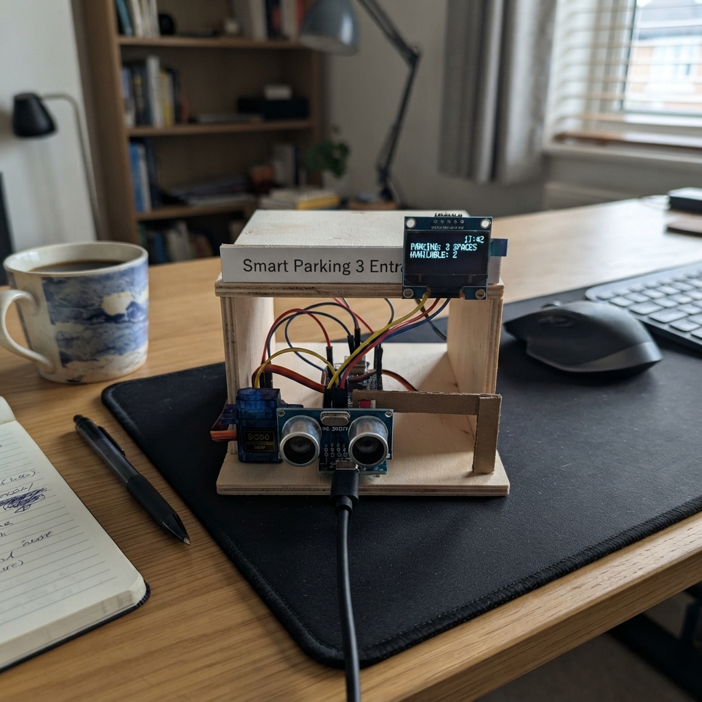
This smart parking system automates entry control for a three-lane parking facility using ultrasonic sensors to detect approaching vehicles and servo-controlled barriers to grant or deny access. The ESP32 microcontroller monitors each lane independently, displaying real-time occupancy status on an OLED screen while managing barrier positions based on vehicle detection.
The guide provides a complete wiring diagram, parts list, and step-by-step assembly instructions to build the system from scratch. Included firmware handles distance sensing, barrier automation, and dashboard display updates, allowing makers to deploy a functional parking management solution with minimal additional coding.
Wiring diagram
Gather all the parts
Assemble it in 6 steps
1. Place the controller and power supply
Put the ESP32 DevKit and the USB-C 5 V power adapter where the three barrier wires can reach. Leave the ESP32 unplugged while you connect wires.
- Use a regulated adapter rated for at least 2 A, because a moving barrier motor can briefly pull extra current.
- Do not power the three motors from the ESP32 3V3 pin — the board can reset or be damaged.
2. Connect the three car sensors
For each HC-SR04P sensor, connect VCC to the ESP32 3V3 pin and GND to ESP32 GND. Connect entry_sensor_1 TRIG to GPIO27 and ECHO to GPIO26; entry_sensor_2 TRIG to GPIO33 and ECHO to GPIO32; entry_sensor_3 TRIG to GPIO25 and ECHO to GPIO17. Point each sensor across its own entrance at the place where a vehicle will stop.
- VCC → 3V3 (power); GND → GND (ground); TRIG and ECHO are the two signal wires.
- Keep the front openings of the sensors clear so the sound pulses are not blocked by the barrier arm.
- Use HC-SR04P sensors, which work safely with the ESP32's 3.3 V signal pins; a standard 5 V HC-SR04 ECHO wire needs a voltage divider before it reaches the ESP32.
3. Connect the parking display
Connect the OLED VCC pin to ESP32 3V3 and its GND pin to ESP32 GND. Connect SDA to GPIO21 and SCL to GPIO22. This small screen shows whether each entrance has a car and whether its barrier is open.
- VCC → 3V3 (power), GND → GND (ground), SDA → GPIO21 (data), SCL → GPIO22 (clock).
- Make sure VCC and GND are not swapped — swapped power can damage the screen.
4. Wire the three barrier motors
On each SG90 servo, connect the brown or black wire to the shared GND, the red wire to the separate 5 V adapter, and the orange or yellow wire to the ESP32: GPIO13 for barrier_servo_1, GPIO14 for barrier_servo_2, and GPIO16 for barrier_servo_3. Fit a lightweight barrier arm to each servo shaft after checking its closed position.
- Red → 5 V (motor power), brown/black → GND (ground), orange/yellow → the listed GPIO (control signal).
- All grounds must join together: adapter GND, ESP32 GND, sensors, display, and all three servos.
- Do not connect a servo's red wire to 3V3. A servo can pull enough current to make the ESP32 restart.
5. Make the shared power connection
Connect the USB-C adapter +5V output to the shared 5 V rail that feeds the three servo red wires and the ESP32 5V/VIN pin. Connect the adapter GND output to the shared ground rail. The ESP32 can then be connected to USB for programming while every part still shares the same ground.
- +5V → ESP32 5V/VIN and servo red wires (power); GND → ESP32 GND and every black/brown wire (ground).
- Never connect two different powered USB supplies to the ESP32 at the same time unless their 5 V outputs are safely isolated; use one 5 V source for the finished installation.
6. Test the barrier positions
With each barrier arm able to move freely, plug in the ESP32 and power supply. After deployment, hold an object about 10 to 25 cm in front of one sensor. That entrance should show CAR - OPEN and its matching barrier should raise; move the object away and the barrier should close.
- Test one entrance at a time so you can confirm the matching sensor and barrier pair.
- If an arm points the wrong way, remove it from the servo spline and refit it while the servo is in its closed position.
- Keep fingers clear of the moving arms while testing; a servo can move suddenly when power is first applied.
Review all connections
1. Connections between "entry_sensor_1" and "ESP32"
2. Connections between "entry_sensor_2" and "ESP32"
3. Connections between "entry_sensor_3" and "ESP32"
4. Connections between "barrier_servo_1" and "ESP32"
5. Connections between "barrier_servo_2" and "ESP32"
6. Connections between "barrier_servo_3" and "ESP32"
7. Connections between "status_oled" and "ESP32"
8. Connections between "servo_power_supply" and "ESP32"
Deploy the firmware
#include <Arduino.h>
#include <Wire.h>
#include <ESP32Servo.h>
#include <Adafruit_GFX.h>
#include <Adafruit_SSD1306.h>


// Forward declarations
long readDistanceCm(uint8_t lane);
void drawDashboard();

constexpr int SENSOR1_TRIG = 27;
constexpr int SENSOR1_ECHO = 26;
constexpr int SENSOR2_TRIG = 33;
constexpr int SENSOR2_ECHO = 32;
constexpr int SENSOR3_TRIG = 25;
constexpr int SENSOR3_ECHO = 17;
constexpr int SERVO1_PIN = 13;
constexpr int SERVO2_PIN = 14;
constexpr int SERVO3_PIN = 16;
constexpr int OLED_SDA = 21;
constexpr int OLED_SCL = 22;

constexpr uint8_t SCREEN_WIDTH = 128;
constexpr uint8_t SCREEN_HEIGHT = 64;
constexpr uint16_t CAR_DISTANCE_CM = 25;
constexpr uint16_t OPEN_ANGLE = 90;
constexpr uint16_t CLOSED_ANGLE = 0;
constexpr unsigned long SAMPLE_INTERVAL_MS = 300;

Adafruit_SSD1306 display(SCREEN_WIDTH, SCREEN_HEIGHT, &Wire, -1);
Servo barriers[3];
const int trigPins[3] = {SENSOR1_TRIG, SENSOR2_TRIG, SENSOR3_TRIG};
const int echoPins[3] = {SENSOR1_ECHO, SENSOR2_ECHO, SENSOR3_ECHO};
bool laneOccupied[3] = {false, false, false};
bool shownOccupied[3] = {true, true, true};
unsigned long lastSampleMs = 0;

long readDistanceCm(uint8_t lane) {
  digitalWrite(trigPins[lane], LOW);
  delayMicroseconds(3);
  digitalWrite(trigPins[lane], HIGH);
  delayMicroseconds(10);
  digitalWrite(trigPins[lane], LOW);

  unsigned long duration = pulseIn(echoPins[lane], HIGH, 25000UL);
  if (duration == 0) return 999;
  return duration / 58;
}

void drawDashboard() {
  display.clearDisplay();
  display.setTextColor(SSD1306_WHITE);
  display.setTextSize(1);
  display.setCursor(0, 0);
  display.println("SMART PARKING");
  display.drawLine(0, 11, 127, 11, SSD1306_WHITE);

  uint8_t freeEntrances = 0;
  for (uint8_t lane = 0; lane < 3; lane++) {
    uint8_t y = 17 + lane * 15;
    display.setCursor(0, y);
    display.print("Entry ");
    display.print(lane + 1);
    display.print(": ");
    display.println(laneOccupied[lane] ? "CAR - OPEN" : "CLEAR - CLOSED");
    if (!laneOccupied[lane]) freeEntrances++;
  }

  display.setCursor(0, 55);
  display.print("Clear entries: ");
  display.print(freeEntrances);
  display.display();
  for (uint8_t lane = 0; lane < 3; lane++) shownOccupied[lane] = laneOccupied[lane];
}

void setup() {
  for (uint8_t lane = 0; lane < 3; lane++) {
    pinMode(trigPins[lane], OUTPUT);
    pinMode(echoPins[lane], INPUT);
    digitalWrite(trigPins[lane], LOW);
  }

  barriers[0].attach(SERVO1_PIN);
  barriers[1].attach(SERVO2_PIN);
  barriers[2].attach(SERVO3_PIN);
  for (uint8_t lane = 0; lane < 3; lane++) barriers[lane].write(CLOSED_ANGLE);

  Wire.begin(OLED_SDA, OLED_SCL);
  if (!display.begin(SSD1306_SWITCHCAPVCC, 0x3C)) {
    while (true) delay(1000);
  }
  drawDashboard();
}

void loop() {
  if (millis() - lastSampleMs < SAMPLE_INTERVAL_MS) return;
  lastSampleMs = millis();

  bool displayChanged = false;
  for (uint8_t lane = 0; lane < 3; lane++) {
    long distance = readDistanceCm(lane);
    bool carPresent = distance > 2 && distance <= CAR_DISTANCE_CM;
    if (carPresent != laneOccupied[lane]) {
      laneOccupied[lane] = carPresent;
      barriers[lane].write(carPresent ? OPEN_ANGLE : CLOSED_ANGLE);
      displayChanged = true;
    }
  }
  if (displayChanged) drawDashboard();
}
Remix this project
Make it yours in one click
Open a full copy of this project in your own Schematik workspace — diagram, code, parts, and assembly steps included. Swap the sensor, add features, or redesign the whole thing with AI. The author's original stays untouched.