Community project
Make Me Flliper Zero
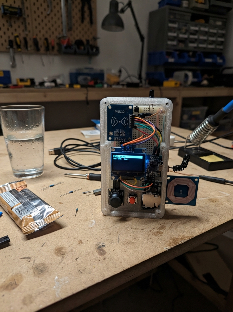
This project builds a handheld multi-protocol scanner and emulator powered by an ESP32, capable of capturing and replaying infrared signals, reading NFC tags, RFID cards, iButton keys, and monitoring sub-GHz radio traffic. The device combines a 128x64 OLED display, dual-axis joystick control, and storage on microSD card to create a portable tool for exploring wireless protocols and RF devices.
The guide provides a complete wiring diagram connecting all sensors and modules to the ESP32, a full parts list with recommended suppliers, Arduino firmware that handles IR capture/playback, NFC polling, RFID reading, and radio monitoring through an intuitive menu system, and step-by-step assembly instructions from component layout through case closure and first-time operation.
Wiring diagram

Gather all the parts
Assemble it in 8 steps
1. Lay out the handheld parts
Place the ESP32, screen, joystick, clear button, infrared receiver, NFC board, RFID reader, iButton probe, radio board, microSD board, and battery parts where they will fit in the plastic case. Keep the NFC board, RFID antenna, infrared receiver, infrared LED, iButton probe, microSD slot, and joystick facing their planned case openings.
- Use a non-metallic plastic case; metal can greatly reduce NFC, RFID, and radio range.
- Do a dry fit before drilling or gluing anything.
- Do not connect the battery while arranging parts; loose wires can short and heat up.
2. Wire the 3.3 volt parts
Connect OLED VCC, infrared receiver VCC, joystick VCC, PN532 VCC, CC1101 VCC, and microSD VCC to ESP32 3V3 (power). Connect each of their GND pins to ESP32 GND (ground). Connect OLED SDA and PN532 SDA together to GPIO21 (data), and OLED SCL and PN532 SCL together to GPIO22 (clock). Set both PN532 I2C switches to ON before powering it.
- Keep the shared screen and NFC wires short.
- The printed VCC, GND, SDA, and SCL labels—not the physical left-to-right order—tell you where each wire goes.
- Use 3V3, never 5V, for the PN532, CC1101, joystick, OLED, and microSD module. A 5V signal can damage ESP32 inputs.
3. Wire the controls and infrared receiver
Connect infrared receiver OUT to GPIO27 (signal). Connect joystick VRx to GPIO32 (left-right signal), VRy to GPIO33 (up-down signal), and SW to GPIO14 (press signal). Place the clear button across the breadboard center gap; connect one side to GPIO26 (signal) and the opposite side to GND (ground).
- The joystick press and clear button use the board's built-in pull-up, so they need no extra resistor.
- If a button always reads as pressed, use a leg on the opposite side of the button.
- Check the infrared receiver's printed VCC, GND, and OUT labels carefully; different receiver boards put those pins in different physical orders.
4. Wire the microSD card and receive-only radio
Connect microSD MOSI and CC1101 MOSI together to GPIO23 (data), both MISO pins to GPIO19 (data), and both SCK pins to GPIO18 (clock). Connect CC1101 CSN to GPIO4 (its private select signal) and microSD CS to GPIO13 (its private select signal). Fit the antenna supplied for your locally legal receive frequency to the CC1101 board.
- The three shared wires are normal; the two separate CS wires let the ESP32 choose one board at a time.
- Use the project only to receive signals you are entitled to examine.
- Do not transmit with the CC1101 in this build. Radio rules and permitted frequencies vary by location.
5. Wire the low-frequency tag readers
Connect the RDM6300 VCC to the regulated 5V supply (power) and its GND to shared GND (ground). Build its safety divider: RDM6300 TX to the 10 kΩ resistor, join that resistor's far end to one end of the 20 kΩ resistor, connect that joined point to GPIO16 (signal), and connect the other 20 kΩ resistor end to GND. Connect iButton probe DATA to GPIO17 (signal) and GND to shared GND; connect the 4.7 kΩ resistor between GPIO17 and 3V3 (pull-up).
- The two RFID resistors reduce the reader's 5V data output to a safe 3.3V-level signal for the ESP32.
- This reads tag identifiers only; do not use it to copy or impersonate credentials.
- Never connect the RDM6300 TX wire directly to GPIO16; its 5V output can damage the ESP32.
6. Build the infrared sending stage
Connect GPIO25 to one end of the 1 kΩ resistor, then connect its other end to the 2N2222 BASE (control). Connect the transistor EMITTER to GND (ground). Connect the infrared LED cathode, the short leg, to the transistor COLLECTOR. Connect 3V3 through the 100 Ω resistor to the infrared LED anode, the long leg (power).
- Aim the LED through a small hole in the case.
- The infrared light is invisible; test only with an appliance you own.
- Do not reverse the LED or transistor connections. Reversed parts may not work and can become damaged.
7. Build the rechargeable power chain
Connect battery positive to TP4056 B+ (power) and battery negative to TP4056 B- (ground). Connect TP4056 OUT+ to boost converter VIN+ (power) and OUT- to VIN- (ground). Adjust the boost converter to exactly 5.0 V with a meter before connecting it. Connect boost VOUT+ to the ESP32 VIN/5V pin (power) and boost VOUT- to ESP32 GND (ground). The TP4056 IN+ and IN- go only to its own USB charging connector.
- Charge through the TP4056 USB-C connector, not through the ESP32 USB connector.
- Tie and insulate all battery wires so they cannot pull loose in the case.
- A lithium battery can overheat or catch fire if shorted, punctured, or charged incorrectly. Stop immediately if it swells, gets hot, or smells unusual.
- Do not connect the ESP32 USB cable and battery boost output at the same time unless you add proper power isolation.
8. Close the case and use the menus
Secure boards with standoffs or non-conductive foam, keep antennas away from battery wires, and close the case without pinching leads. The left-right joystick movement selects IR, NFC, 125 kHz RFID, iButton, or Sub-GHz receive mode. In IR mode, point a remote you own at the receiver to save its last command; press the joystick to send that saved command to your own appliance. Press the clear button to clear the screen.
- Use only tags, remotes, equipment, and signals you own or are authorized to test.
- The ESP32 DevKit USB connection is for charging/programming and serial communication; this board cannot safely provide native USB keyboard or device impersonation.
- Keep NFC/RFID and radio features read-only. Do not use this project to clone credentials, bypass access controls, or interfere with radio systems.
Review all connections
1. Connections between "oled_1" and "ESP32"
2. Connections between "ir_receiver_1" and "ESP32"
3. Connections between "joystick_1" and "ESP32"
4. Connections between "button_clear" and "ESP32"
5. Connections between "pn532_1" and "ESP32"
6. Connections between "cc1101_1" and "ESP32"
7. Connections between "microsd_1" and "ESP32"
8. Connections between "rdm6300_1" and "ESP32"
9. Connections between "res_rfid_bottom_1" and "ESP32"
10. Connections between "ibutton_probe_1" and "ESP32"
11. Connections between "res_ibutton_pullup_1" and "ESP32"
12. Connections between "res_base_1" and "ESP32"
13. Connections between "ir_driver_1" and "ESP32"
14. Connections between "res_ir_1" and "ESP32"
15. Connections between "battery_1" and "ESP32"
16. Connections between "charger_1" and "ESP32"
17. Connections between "boost_1" and "ESP32"
18. Connections between "res_rfid_top_1" and "ESP32"
Deploy the firmware
#include <Arduino.h>
#include <Wire.h>
#include <SPI.h>
#include <SD.h>
#include <Adafruit_GFX.h>
#include <Adafruit_SSD1306.h>
#include <Adafruit_PN532.h>
#include <IRremote.hpp>
#include <OneWire.h>
#include <ELECHOUSE_CC1101_SRC_DRV.h>


struct StoredIr {
  uint32_t magic;
  uint8_t protocol;
  uint16_t address;
  uint16_t command;
  uint32_t raw;
};


// Forward declarations
void setStatus(const char *line1, const char *line2);
void drawScreen();
void loadSavedIr();
void saveIr(const IRData &data);
void sendSavedIr();
void pollIr();
void pollNfc();
void pollRfid();
void pollIButton();
void pollRadio();
void handleControls();

constexpr uint8_t OLED_SDA_PIN = 21;
constexpr uint8_t OLED_SCL_PIN = 22;
constexpr uint8_t IR_RECEIVE_PIN = 27;
constexpr uint8_t IR_SEND_PIN = 25;
constexpr uint8_t JOYSTICK_X_PIN = 32;
constexpr uint8_t JOYSTICK_Y_PIN = 33;
constexpr uint8_t JOYSTICK_SW_PIN = 14;
constexpr uint8_t CLEAR_BUTTON_PIN = 26;
constexpr uint8_t RFID_RX_PIN = 16;
constexpr uint8_t IBUTTON_PIN = 17;
constexpr uint8_t SPI_SCK_PIN = 18;
constexpr uint8_t SPI_MISO_PIN = 19;
constexpr uint8_t SPI_MOSI_PIN = 23;
constexpr uint8_t CC1101_CS_PIN = 4;
constexpr uint8_t SD_CS_PIN = 13;
constexpr uint8_t SCREEN_WIDTH = 128;
constexpr uint8_t SCREEN_HEIGHT = 64;
constexpr uint8_t OLED_RESET = 255;
constexpr uint32_t IR_FILE_MAGIC = 0x49525231UL;

Adafruit_SSD1306 display(SCREEN_WIDTH, SCREEN_HEIGHT, &Wire, OLED_RESET);
Adafruit_PN532 nfc(-1, -1, &Wire);
OneWire iButton(IBUTTON_PIN);
HardwareSerial rfidSerial(2);

const char *modeNames[] = {"IR remote", "NFC", "125k RFID", "iButton", "Sub-GHz RX"};
constexpr uint8_t MODE_COUNT = sizeof(modeNames) / sizeof(modeNames[0]);
uint8_t mode = 0;
char statusLine[42] = "Starting...";
char detailLine[42] = "";
bool sdReady = false;
bool nfcReady = false;
bool radioReady = false;
bool haveSavedIr = false;
uint32_t lastInputMs = 0;
uint32_t lastPollMs = 0;


StoredIr savedIr{};

void setStatus(const char *line1, const char *line2 = "") {
  strncpy(statusLine, line1, sizeof(statusLine) - 1);
  statusLine[sizeof(statusLine) - 1] = '\0';
  strncpy(detailLine, line2, sizeof(detailLine) - 1);
  detailLine[sizeof(detailLine) - 1] = '\0';
}

void drawScreen() {
  display.clearDisplay();
  display.setTextColor(SSD1306_WHITE);
  display.setTextSize(1);
  display.setCursor(0, 0);
  display.print(F("Pocket tool: "));
  display.println(modeNames[mode]);
  display.drawLine(0, 10, 127, 10, SSD1306_WHITE);
  display.setCursor(0, 18);
  display.println(statusLine);
  display.setCursor(0, 32);
  display.println(detailLine);
  display.setCursor(0, 49);
  display.println(F("L/R mode  press action"));
  display.println(F("Button clears screen"));
  display.display();
}

void loadSavedIr() {
  if (!sdReady) return;
  File file = SD.open("/lastir.bin", FILE_READ);
  if (file && file.read(reinterpret_cast<uint8_t *>(&savedIr), sizeof(savedIr)) == sizeof(savedIr) && savedIr.magic == IR_FILE_MAGIC) {
    haveSavedIr = true;
  }
  if (file) file.close();
}

void saveIr(const IRData &data) {
  savedIr.magic = IR_FILE_MAGIC;
  savedIr.protocol = static_cast<uint8_t>(data.protocol);
  savedIr.address = data.address;
  savedIr.command = data.command;
  savedIr.raw = data.decodedRawData;
  haveSavedIr = true;
  if (sdReady) {
    SD.remove("/lastir.bin");
    File file = SD.open("/lastir.bin", FILE_WRITE);
    if (file) {
      file.write(reinterpret_cast<const uint8_t *>(&savedIr), sizeof(savedIr));
      file.close();
    }
  }
}

void sendSavedIr() {
  if (!haveSavedIr) {
    setStatus("No saved IR command", "Aim remote at receiver");
    drawScreen();
    return;
  }
  IRData data{};
  data.protocol = static_cast<decode_type_t>(savedIr.protocol);
  data.address = savedIr.address;
  data.command = savedIr.command;
  data.decodedRawData = savedIr.raw;
  IrSender.write(&data, NO_REPEATS);
  setStatus("Sent saved IR command", "Only use on your equipment");
  drawScreen();
}

void pollIr() {
  if (!IrReceiver.decode()) return;
  if (!(IrReceiver.decodedIRData.flags & IRDATA_FLAGS_IS_REPEAT)) {
    saveIr(IrReceiver.decodedIRData);
    snprintf(statusLine, sizeof(statusLine), "Saved protocol %u", static_cast<unsigned>(IrReceiver.decodedIRData.protocol));
    snprintf(detailLine, sizeof(detailLine), "Addr %04X Cmd %04X", IrReceiver.decodedIRData.address, IrReceiver.decodedIRData.command);
    drawScreen();
  }
  IrReceiver.resume();
}

void pollNfc() {
  if (!nfcReady || millis() - lastPollMs < 400) return;
  lastPollMs = millis();
  uint8_t uid[7];
  uint8_t uidLength = 0;
  if (nfc.readPassiveTargetID(PN532_MIFARE_ISO14443A, uid, &uidLength, 30)) {
    char uidText[25] = "UID ";
    for (uint8_t i = 0; i < uidLength && strlen(uidText) < 20; i++) {
      char hex[4];
      snprintf(hex, sizeof(hex), "%02X", uid[i]);
      strcat(uidText, hex);
    }
    setStatus("NFC tag read", uidText);
    drawScreen();
  }
}

void pollRfid() {
  static char tag[15] = "";
  static uint8_t index = 0;
  while (rfidSerial.available()) {
    char c = static_cast<char>(rfidSerial.read());
    if (c == '\n' || c == '\r') {
      if (index > 0) {
        tag[index] = '\0';
        setStatus("125 kHz tag read", tag);
        drawScreen();
        index = 0;
      }
    } else if (isxdigit(c) && index < sizeof(tag) - 1) {
      tag[index++] = c;
    }
  }
}

void pollIButton() {
  if (millis() - lastPollMs < 600) return;
  lastPollMs = millis();
  uint8_t address[8];
  iButton.reset_search();
  if (iButton.search(address)) {
    char serial[25] = "ROM ";
    for (uint8_t i = 0; i < 8; i++) {
      char hex[4];
      snprintf(hex, sizeof(hex), "%02X", address[i]);
      strcat(serial, hex);
    }
    setStatus("iButton read", serial);
    drawScreen();
  }
}

void pollRadio() {
  if (!radioReady || millis() - lastPollMs < 250) return;
  lastPollMs = millis();
  if (ELECHOUSE_cc1101.CheckRxFifo(0)) {
    byte packet[64];
    byte length = ELECHOUSE_cc1101.ReceiveData(packet);
    snprintf(statusLine, sizeof(statusLine), "RF packet received");
    snprintf(detailLine, sizeof(detailLine), "%u bytes at 433.92 MHz", static_cast<unsigned>(length));
    drawScreen();
  }
}

void handleControls() {
  if (millis() - lastInputMs < 250) return;
  int x = analogRead(JOYSTICK_X_PIN);
  if (x < 800 || x > 3300) {
    mode = x < 800 ? (mode + MODE_COUNT - 1) % MODE_COUNT : (mode + 1) % MODE_COUNT;
    lastInputMs = millis();
    setStatus("Select a function", "Bring your own tag/device");
    drawScreen();
  }
  if (digitalRead(CLEAR_BUTTON_PIN) == LOW) {
    lastInputMs = millis();
    setStatus("Ready", mode == 0 ? "Press stick to send saved IR" : "Waiting for a nearby tag");
    drawScreen();
  }
  if (digitalRead(JOYSTICK_SW_PIN) == LOW) {
    lastInputMs = millis();
    if (mode == 0) sendSavedIr();
  }
}

void setup() {
  pinMode(CLEAR_BUTTON_PIN, INPUT_PULLUP);
  pinMode(JOYSTICK_SW_PIN, INPUT_PULLUP);
  Wire.begin(OLED_SDA_PIN, OLED_SCL_PIN);
  display.begin(SSD1306_SWITCHCAPVCC, 0x3C);
  SPI.begin(SPI_SCK_PIN, SPI_MISO_PIN, SPI_MOSI_PIN);
  sdReady = SD.begin(SD_CS_PIN);
  loadSavedIr();

  IrReceiver.begin(IR_RECEIVE_PIN, DISABLE_LED_FEEDBACK);
  IrSender.begin(IR_SEND_PIN, DISABLE_LED_FEEDBACK);
  rfidSerial.begin(9600, SERIAL_8N1, RFID_RX_PIN, -1);

  nfc.begin();
  uint32_t version = nfc.getFirmwareVersion();
  nfcReady = version != 0;
  if (nfcReady) nfc.SAMConfig();

  ELECHOUSE_cc1101.setSpiPin(SPI_SCK_PIN, SPI_MISO_PIN, SPI_MOSI_PIN, CC1101_CS_PIN);
  ELECHOUSE_cc1101.Init();
  radioReady = true;
  ELECHOUSE_cc1101.setMHZ(433.92);
  ELECHOUSE_cc1101.SetRx();
  setStatus("Ready", "L/R chooses a function");
  drawScreen();
}

void loop() {
  handleControls();
  if (mode == 0) pollIr();
  else if (mode == 1) pollNfc();
  else if (mode == 2) pollRfid();
  else if (mode == 3) pollIButton();
  else pollRadio();
}
Remix this project
Make it yours in one click
Open a full copy of this project in your own Schematik workspace — diagram, code, parts, and assembly steps included. Swap the sensor, add features, or redesign the whole thing with AI. The author's original stays untouched.