Community project
Med Matrix Sentinel Wearable
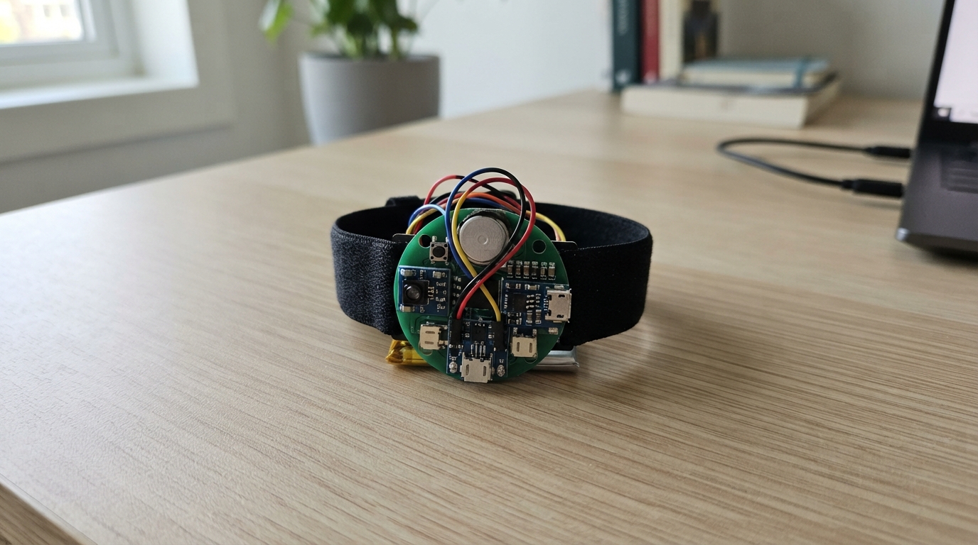
The Med Matrix Sentinel is a wearable health monitoring device built around an ESP32 that tracks vital signs, environmental conditions, and motion to detect potential health emergencies. It combines a pulse oximetry sensor, temperature monitoring, air quality detection, and accelerometer-based fall detection into a compact wrist-worn form factor that communicates via Bluetooth Low Energy.
This guide provides a complete wiring diagram, parts list, and step-by-step assembly instructions for building the Sentinel from scratch. The firmware handles sensor multiplexing across multiple I2C devices, processes heart rate and blood oxygen data, evaluates risk conditions, and triggers haptic feedback alerts or emergency notifications through an SOS button interface.
Wiring diagram

Gather all the parts
Assemble it in 5 steps
1. Place the watch parts in the case
Put the MAX30102 sensor through the opening on the back of the watch so its clear window rests gently against the wrist. Put the TMP117 beside it, away from the battery. Place the BME280 and BMV080 behind separate mesh-covered side openings so outside air can reach them. Place the small TCA9548A switch inside the case near the sensor boards.
- A soft black foam ring around the MAX30102 opening blocks stray light and helps pulse readings during movement.
- Keep both air openings clear of glue, strap material, and clothing.
- Do not make medical decisions from the optical readings; this prototype looks for unusual patterns and alerts.
- Do not seal the BME280 or BMV080 inside the case, because trapped warm air gives incorrect local-air readings.
2. Build the safe battery path
Connect LiPo POSITIVE to TP4056 B+ (battery power) and LiPo NEGATIVE to TP4056 B− (battery ground). Connect TP4056 OUT+ to the 3.3 V regulator VIN (power), and TP4056 OUT− to regulator GND (ground). Use the regulator VOUT as the watch 3V3 rail and join all GND connections together.
- Use the TP4056 USB-C socket when charging the battery.
- Before attaching the watch electronics, measure the regulator output with a multimeter; it should be close to 3.3 V.
- Do not connect the LiPo directly to the XIAO charging pads; use the TP4056 board so the battery is charged safely.
- Stop using the battery if it becomes hot, swollen, punctured, or damaged; a damaged LiPo can catch fire.
3. Wire the shared I2C sensor wires
Connect TCA9548A VCC to 3V3 (power), GND to GND (ground), SDA to XIAO GPIO6 (data), and SCL to XIAO GPIO7 (clock). Connect TCA9548A SD0 to MAX30102 SDA and SC0 to MAX30102 SCL (separate sensor data and clock). Connect TCA9548A SD1 to BMV080 SDA and SC1 to BMV080 SCL (separate particle-sensor data and clock). Connect DRV2605L, ADXL345, TMP117, and BME280 SDA to GPIO6 and SCL to GPIO7 (shared data and clock). Connect each module power pin to 3V3 and each ground pin to GND.
- Keep the GPIO6 and GPIO7 wires short and run them together.
- Leave the MAX30102 INT pin unconnected for this prototype.
- All sensors use 3.3 V only; a higher voltage can damage them.
- The TCA9548A is required because MAX30102 and BMV080 use the same I2C address; bypassing it stops the watch from talking reliably to both sensors.
4. Wire the SOS button and vibration motor
Connect one SOS button leg to XIAO GPIO4 (signal) and the other leg to GND (ground). Connect the two coin-motor leads to DRV2605L OUT+ and OUT− (motor drive).
- A two-second button hold requests help and makes the watch vibrate.
- Either motor lead can go to either motor output because the vibration direction does not matter.
- Do not connect the coin motor directly to a XIAO pin; the DRV2605L drives it safely.
5. Close and test the screenless watch
Leave the TP4056 USB-C socket reachable for charging, keep the BME280 and BMV080 mesh vents open, and close the case without squeezing battery wires. Wear the MAX30102 against the wrist, pair the watch with the nearby phone over Bluetooth, and test a two-second SOS-button hold.
- The vibration motor is the only on-watch alert; there is no display.
- The paired phone must be nearby and connected to mobile data or Wi-Fi to forward an SOS to someone remotely.
- Without GSM, the watch cannot independently send a remote emergency message; without a nearby paired phone it can only vibrate locally.
- Do not wear or charge the open prototype in rain or near flammable vapors.
Review all connections
1. Connections between "lipo_battery" and "ESP32"
2. Connections between "lipo_charger" and "ESP32"
3. Connections between "logic_regulator_3v3" and "ESP32"
4. Connections between "ppg_max30102" and "ESP32"
5. Connections between "haptic_drv2605l" and "ESP32"
6. Connections between "imu_adxl345" and "ESP32"
7. Connections between "temp_tmp117" and "ESP32"
8. Connections between "pm_bmv080" and "ESP32"
9. Connections between "sos_button" and "ESP32"
10. Connections between "env_bme280" and "ESP32"
11. Connections between "i2c_mux" and "ESP32"
Deploy the firmware
#include <Arduino.h>
#include <Wire.h>
#include <BLEDevice.h>
#include <BLEServer.h>
#include <BLEUtils.h>
#include <BLE2902.h>
#include <Adafruit_TCA9548A.h>
#include <Adafruit_DRV2605.h>
#include <Adafruit_ADXL345_U.h>
#include <Adafruit_TMP117.h>
#include <Adafruit_BME280.h>
#include <SparkFun_BMV080_Arduino_Library.h>
#include <MAX30105.h>
#include "heartRate.h"


// Forward declarations
void selectMuxChannel(uint8_t channel);
int pm25ToAqi(float p);
void buzz(uint8_t effect);
void publish();
void setRisk(const String &nextRisk);
void emergency(const char *reason);
void sampleVitalsAndMotion();
void sampleAir();
void evaluate();
void setupBle();

constexpr int I2C_SDA = 6;
constexpr int I2C_SCL = 7;
constexpr int SOS_BUTTON_PIN = 4;
constexpr uint8_t PPG_CHANNEL = 0;
constexpr uint8_t PM_CHANNEL = 1;
constexpr uint8_t BMV080_ADDR = 0x57;
constexpr uint8_t BME280_ADDR = 0x77;
constexpr uint32_t SAMPLE_MS = 25;
constexpr uint32_t AIR_MS = 1000;
constexpr uint32_t SOS_HOLD_MS = 2000;
constexpr float FALL_G = 2.35f;
constexpr float HIGH_SKIN_C = 38.0f;
constexpr float HIGH_AMBIENT_C = 40.0f;
constexpr uint32_t FINGER_IR_MIN = 50000;
const char BLE_SERVICE_UUID[] = "6b5b1c4d-6b86-4d4b-8b19-5f1c3a020001";
const char BLE_STATUS_UUID[] = "6b5b1c4d-6b86-4d4b-8b19-5f1c3a020002";

Adafruit_TCA9548A i2cMux;
Adafruit_DRV2605 haptic;
Adafruit_ADXL345_Unified accel(12345);
Adafruit_TMP117 tmp117;
Adafruit_BME280 bme;
SparkFunBMV080 bmv080;
MAX30105 ppg;
BLECharacteristic *statusChar = nullptr;
bool muxOK = false;
bool hapticOK = false;
bool accelOK = false;
bool tmpOK = false;
bool bmeOK = false;
bool pmOK = false;
bool ppgOK = false;
bool sos = false;
bool alertSent = false;
uint32_t buttonAt = 0;
uint32_t lastSample = 0;
uint32_t lastAir = 0;
uint32_t lastBeat = 0;
float hr = 0;
float spo2 = 0;
float skinC = 0;
float ambientC = 0;
float humidity = 0;
float pm25 = 0;
float motionG = 1;
int aqi = -1;
String risk = "STARTING";
String alertReason = "";

void selectMuxChannel(uint8_t channel) {
  if (!muxOK) return;
  i2cMux.closeAll();
  i2cMux.openChannel(channel);
}

int pm25ToAqi(float p) {
  if (p < 0) return -1;
  struct Band { float low; float high; int aqiLow; int aqiHigh; };
  const Band bands[] = {{0, 12, 0, 50}, {12.1f, 35.4f, 51, 100}, {35.5f, 55.4f, 101, 150}, {55.5f, 150.4f, 151, 200}, {150.5f, 250.4f, 201, 300}, {250.5f, 350.4f, 301, 400}, {350.5f, 500.4f, 401, 500}};
  p = floorf(p * 10.0f) / 10.0f;
  if (p > 500.4f) return 500;
  for (const auto &band : bands) {
    if (p >= band.low && p <= band.high) {
      return round(((float)(band.aqiHigh - band.aqiLow) / (band.high - band.low)) * (p - band.low) + band.aqiLow);
    }
  }
  return -1;
}

void buzz(uint8_t effect) {
  if (!hapticOK) return;
  haptic.setWaveform(0, effect);
  haptic.setWaveform(1, 0);
  haptic.go();
}

void publish() {
  if (!statusChar) return;
  String message = "state=" + risk + ",reason=" + alertReason + ",hr=" + String(hr, 0) + ",spo2=" + String(spo2, 0) + ",skinC=" + String(skinC, 1) + ",ambientC=" + String(ambientC, 1) + ",humidity=" + String(humidity, 0) + ",pm25=" + String(pm25, 1) + ",aqi=" + String(aqi);
  statusChar->setValue(message.c_str());
  statusChar->notify();
}

void setRisk(const String &nextRisk) {
  if (nextRisk == risk) return;
  risk = nextRisk;
  if (risk == "SOS") buzz(82);
  else if (risk == "ALERT") buzz(47);
  publish();
}

void emergency(const char *reason) {
  if (alertSent) return;
  alertSent = true;
  alertReason = reason;
  setRisk("SOS");
}

void sampleVitalsAndMotion() {
  if (ppgOK) {
    selectMuxChannel(PPG_CHANNEL);
    ppg.check();
    while (ppg.available()) {
      uint32_t ir = ppg.getIR();
      if (ir > FINGER_IR_MIN && checkForBeat(ir)) {
        uint32_t now = millis();
        if (lastBeat != 0) {
          float bpm = 60.0f / ((now - lastBeat) / 1000.0f);
          if (bpm >= 35.0f && bpm <= 220.0f) hr = (hr == 0) ? bpm : (0.8f * hr + 0.2f * bpm);
        }
        lastBeat = now;
      }
      if (ir <= FINGER_IR_MIN) {
        hr = 0;
        spo2 = 0;
        lastBeat = 0;
      }
      ppg.nextSample();
    }
  }
  if (accelOK) {
    sensors_event_t event;
    accel.getEvent(&event);
    motionG = sqrtf(event.acceleration.x * event.acceleration.x + event.acceleration.y * event.acceleration.y + event.acceleration.z * event.acceleration.z) / SENSORS_GRAVITY_STANDARD;
    if (motionG >= FALL_G) emergency("possible fall");
  }
  if (tmpOK) {
    sensors_event_t event;
    tmp117.getEvent(&event);
    if (event.temperature > 15 && event.temperature < 45) skinC = event.temperature;
  }
}

void sampleAir() {
  if (millis() - lastAir < AIR_MS) return;
  lastAir = millis();
  if (bmeOK) {
    float nextAmbientC = bme.readTemperature();
    float nextHumidity = bme.readHumidity();
    if (!isnan(nextAmbientC) && nextAmbientC > -20 && nextAmbientC < 70) ambientC = nextAmbientC;
    if (!isnan(nextHumidity) && nextHumidity >= 0 && nextHumidity <= 100) humidity = nextHumidity;
  }
  if (pmOK) {
    selectMuxChannel(PM_CHANNEL);
    if (bmv080.readSensor()) {
      pm25 = bmv080.PM25();
      aqi = pm25ToAqi(pm25);
    }
  }
  publish();
}

void evaluate() {
  if (sos || alertSent) return;
  bool risky = hr >= 130 || (hr >= 35 && hr <= 40) || skinC >= HIGH_SKIN_C || ambientC >= HIGH_AMBIENT_C || aqi >= 151;
  alertReason = risky ? "health, heat, or air-quality warning" : "";
  setRisk(risky ? "ALERT" : "OK");
}

void setupBle() {
  BLEDevice::init("MedMatrix-Sentinel");
  BLEServer *server = BLEDevice::createServer();
  BLEService *service = server->createService(BLE_SERVICE_UUID);
  statusChar = service->createCharacteristic(BLE_STATUS_UUID, BLECharacteristic::PROPERTY_READ | BLECharacteristic::PROPERTY_NOTIFY);
  statusChar->addDescriptor(new BLE2902());
  service->start();
  BLEAdvertising *advertising = BLEDevice::getAdvertising();
  advertising->addServiceUUID(BLE_SERVICE_UUID);
  advertising->start();
}

void setup() {
  Serial.begin(115200);
  pinMode(SOS_BUTTON_PIN, INPUT_PULLUP);
  Wire.begin(I2C_SDA, I2C_SCL);
  Wire.setClock(400000);
  muxOK = i2cMux.begin(0x70, &Wire);
  if (muxOK) {
    selectMuxChannel(PPG_CHANNEL);
    ppgOK = ppg.begin(Wire, I2C_SPEED_FAST);
    if (ppgOK) ppg.setup(0x1F, 4, 2, 100, 411, 4096);
    selectMuxChannel(PM_CHANNEL);
    pmOK = bmv080.begin(BMV080_ADDR, Wire);
    if (pmOK) {
      bmv080.init();
      pmOK = bmv080.setMode(SF_BMV080_MODE_CONTINUOUS);
    }
    i2cMux.closeAll();
  }
  hapticOK = haptic.begin();
  if (hapticOK) haptic.selectLibrary(1);
  accelOK = accel.begin();
  if (accelOK) accel.setRange(ADXL345_RANGE_16_G);
  tmpOK = tmp117.begin();
  bmeOK = bme.begin(BME280_ADDR, &Wire);
  setupBle();
  setRisk("OK");
  buzz(1);
}

void loop() {
  uint32_t now = millis();
  if (digitalRead(SOS_BUTTON_PIN) == LOW) {
    if (!buttonAt) buttonAt = now;
    if (!sos && now - buttonAt >= SOS_HOLD_MS) {
      sos = true;
      emergency("SOS button held");
    }
  } else {
    buttonAt = 0;
    sos = false;
  }
  if (now - lastSample >= SAMPLE_MS) {
    lastSample = now;
    sampleVitalsAndMotion();
    sampleAir();
    evaluate();
  }
}
Remix this project
Make it yours in one click
Open a full copy of this project in your own Schematik workspace — diagram, code, parts, and assembly steps included. Swap the sensor, add features, or redesign the whole thing with AI. The author's original stays untouched.