Community project
Multi-Display Digital Clock
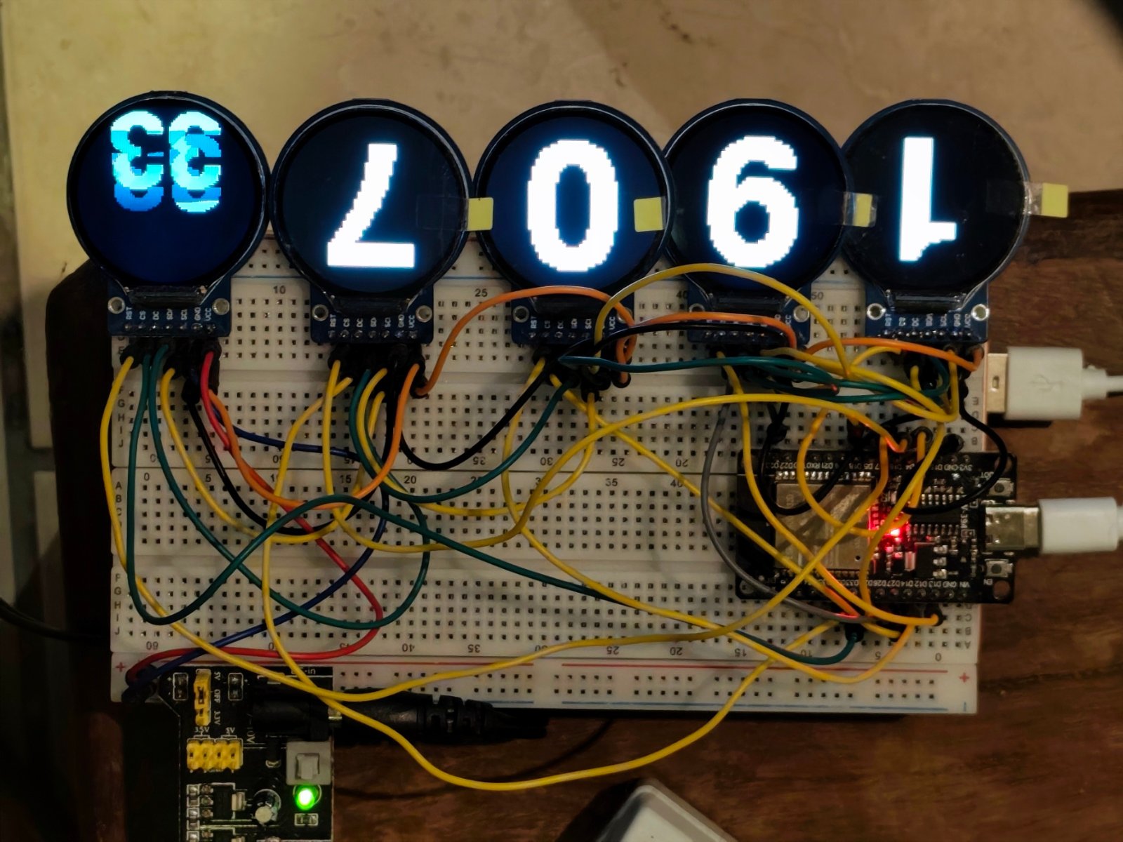
This project builds a multi-display digital clock using five 1.28-inch round TFT screens driven by a single ESP32 microcontroller. Each circular display can show different time information—hours, minutes, seconds, date, or status messages—creating a striking visual timepiece that syncs with network time via WiFi.
The guide provides a complete wiring diagram showing how to connect all five GC9A01 screens to the ESP32 using shared SPI data lines and individual chip-select pins, a full parts list, ready-to-deploy firmware with WiFi time synchronization, and step-by-step assembly instructions for breadboard construction.
Wiring diagram

Gather all the parts
Assemble it in 5 steps
1. Place the ESP32 and screen supply
Put the ESP32 on the breadboard and plug it into its usual USB cable; this USB cable powers only the ESP32. Set the separate 3.3 V power board to its regulated 3.3 V output and power that board from its own USB input. Do not connect the power board’s 3.3 V output to the ESP32 3V3 pin.
- Use red wire only for the separate supply board’s 3.3 V rail and black wire for its ground rail.
- Use a supply board rated for at least 1 A at 3.3 V so the five lit screens have enough power.
- Do not set the screen power board to 5 V — 5 V on a 3.3 V screen can damage it.
- The ESP32 USB cable and the separate screen supply must share ground; without this, the picture signals have no common reference and the screens will not work reliably.
2. Power the five screens from the separate supply
Connect the separate supply board’s 3V3 OUT to every display VCC (power), every display BL, LED, or BLK pin (backlight), and every display RST pin (keeps the screen enabled). Connect its GND to every display GND (ground), then run one more black wire from that same supply GND rail to any ESP32 GND pin (common ground).
- Solderless breadboard rails can be split in the middle, so check with a short wire that the 3.3 V and GND rails reach all five screens.
- Power one screen first if you want to check the rail voltage with a meter before connecting the other four.
- Make sure VCC and GND are not swapped — swapped power can damage a screen.
- Do not join the separate supply’s 3.3 V output to ESP32 3V3 while the ESP32 is powered by USB; only join their GND pins.
3. Share the picture wires
Connect every display SCK or SCL pin to ESP32 GPIO18 (clock), and every display MOSI, DIN, or SDA pin to ESP32 GPIO23 (picture data). These signal wires remain exactly as before; they carry the picture information from the ESP32 to each screen.
- SCK may be printed as SCL, and MOSI may be printed as DIN or SDA, on a display module.
- Use a junction row to split GPIO18 and GPIO23 cleanly to all five screens.
- Do not connect a display MISO pin if it has one; this build only sends data to the screens.
4. Give each screen its own select wires
Label the screens 1 to 5 from left to right. Connect display_1 CS to GPIO4 (select) and DC to GPIO25 (picture-command control). Connect display_2 CS to GPIO13 (select) and DC to GPIO26 (picture-command control). Connect display_3 CS to GPIO14 (select) and DC to GPIO27 (picture-command control). Connect display_4 CS to GPIO16 (select) and DC to GPIO32 (picture-command control). Connect display_5 CS to GPIO17 (select) and DC to GPIO33 (picture-command control).
- Put a small tape label on each screen before wiring CS and DC.
- Read the labels printed on your own board rather than relying on the header-pin order.
- Keep every CS wire separate — joining two CS pins can make both screens react together and scramble the picture.
5. Power up and deploy the clock
First turn on the separate screen supply, then plug the ESP32 into USB. Check that all five backlights come on and no module becomes hot. The ESP32 will connect to Wi-Fi, set Irish time, and then cycle between the time and the two weather views. Press Deploy in Schematik to put the saved clock program on the ESP32.
- If a screen is dark, check its VCC, GND, BL/LED, and its own CS wire first.
- If all screens are dark or random, check the single black wire joining screen-supply GND to ESP32 GND.
- Unplug both USB supplies before moving jumper wires so a loose wire does not short the 3.3 V rail.
Review all connections
1. Connections between "display_1" and "ESP32"
2. Connections between "display_2" and "ESP32"
3. Connections between "display_3" and "ESP32"
4. Connections between "display_4" and "ESP32"
5. Connections between "display_5" and "ESP32"
6. Connections between "screen_supply" and "ESP32"
Deploy the firmware
#include <Arduino.h>
#include <SPI.h>
#include <WiFi.h>
#include <time.h>
#include <Adafruit_GFX.h>
#if defined(ESP32)
#include <Fonts/FreeSansBold24pt7b.h>
#endif
#include <Adafruit_GC9A01A.h>


// Forward declarations

// Forward declarations
void prepareText(Adafruit_GC9A01A &screen, uint16_t color, uint8_t size);
void finishText(Adafruit_GC9A01A &screen);
void drawRollingText(Adafruit_GC9A01A &screen, const char *oldText, const char *newText, uint16_t color, uint8_t size, bool animate);

void drawCentered(Adafruit_GC9A01A &screen, const char *text, uint16_t color, uint8_t size);
void drawDigit(Adafruit_GC9A01A &screen, char digit, bool secondsScreen);
void showTime(const tm &now);
void showDate(const tm &now);
void showStatus(const char *message, uint16_t color);
bool connectAndUpdateTime();

// Enter your Wi-Fi details here before deploying if you want automatic time updates.
constexpr char WIFI_SSID[] = "YOUR_WIFI_NAME";
constexpr char WIFI_PASSWORD[] = "YOUR_WIFI_PASSWORD";
constexpr char IRELAND_TIME_ZONE[] = "GMT0BST,M3.5.0/1,M10.5.0/2";
constexpr uint32_t TIME_SYNC_INTERVAL_MS = 60UL * 60UL * 1000UL;

constexpr int TFT_SCK = 18;
constexpr int TFT_MOSI = 23;
constexpr int TFT1_CS = 4;
constexpr int TFT1_DC = 25;
constexpr int TFT2_CS = 13;
constexpr int TFT2_DC = 26;
constexpr int TFT3_CS = 14;
constexpr int TFT3_DC = 27;
constexpr int TFT4_CS = 16;
constexpr int TFT4_DC = 32;
constexpr int TFT5_CS = 17;
constexpr int TFT5_DC = 33;

Adafruit_GC9A01A screen1(TFT1_CS, TFT1_DC, -1);
Adafruit_GC9A01A screen2(TFT2_CS, TFT2_DC, -1);
Adafruit_GC9A01A screen3(TFT3_CS, TFT3_DC, -1);
Adafruit_GC9A01A screen4(TFT4_CS, TFT4_DC, -1);
Adafruit_GC9A01A screen5(TFT5_CS, TFT5_DC, -1);
Adafruit_GC9A01A *screens[] = {&screen1, &screen2, &screen3, &screen4, &screen5};

char lastShown[4] = {'\0', '\0', '\0', '\0'};
int lastSeconds = -1;
uint32_t lastTimePollMs = 0;
uint32_t lastTimeSyncMs = 0;
bool showingDate = false;

constexpr uint8_t ROLLER_FRAMES = 8;
constexpr uint16_t ROLLER_FRAME_MS = 50;

void prepareText(Adafruit_GC9A01A &screen, uint16_t color, uint8_t size) {
  screen.setTextWrap(false);
#if defined(ESP32)
  screen.setFont(&FreeSansBold24pt7b);
#endif
  screen.setTextSize(size);
  screen.setTextColor(color);
}

void finishText(Adafruit_GC9A01A &screen) {
#if defined(ESP32)
  screen.setFont(nullptr);
#endif
}

void drawCentered(Adafruit_GC9A01A &screen, const char *text, uint16_t color, uint8_t size) {
  screen.fillScreen(GC9A01A_BLACK);
  prepareText(screen, color, size);
  int16_t x1, y1;
  uint16_t width, height;
  screen.getTextBounds(text, 0, 0, &x1, &y1, &width, &height);
  screen.setCursor((240 - width) / 2 - x1, (240 - height) / 2 - y1);
  screen.print(text);
  finishText(screen);
}

void drawRollingText(Adafruit_GC9A01A &screen, const char *oldText, const char *newText,
                     uint16_t color, uint8_t size, bool animate) {
  prepareText(screen, color, size);
  int16_t x1, y1;
  uint16_t width, height;
  screen.getTextBounds(newText, 0, 0, &x1, &y1, &width, &height);
  const int16_t x = (240 - width) / 2 - x1;
  const int16_t centreY = (240 - height) / 2 - y1;

  const uint8_t frames = animate ? ROLLER_FRAMES : 1;
  for (uint8_t frame = 1; frame <= frames; ++frame) {
    const int16_t travel = (240 * frame) / frames;
    screen.fillScreen(GC9A01A_BLACK);
    if (animate) {
      screen.setCursor(x, centreY - travel);
      screen.print(oldText);
    }
    screen.setCursor(x, centreY + 240 - travel);
    screen.print(newText);
    if (animate) {
      delay(ROLLER_FRAME_MS);
    }
  }
  finishText(screen);
}

void showTime(const tm &now) {
  char digits[4] = {
    static_cast<char>('0' + now.tm_hour / 10),
    static_cast<char>('0' + now.tm_hour % 10),
    static_cast<char>('0' + now.tm_min / 10),
    static_cast<char>('0' + now.tm_min % 10)
  };

  for (int i = 0; i < 4; ++i) {
    if (digits[i] != lastShown[i]) {
      char oldText[2] = {lastShown[i] == '\0' ? digits[i] : lastShown[i], '\0'};
      char newText[2] = {digits[i], '\0'};
      drawRollingText(*screens[i], oldText, newText, GC9A01A_WHITE, 5, lastShown[i] != '\0');
      lastShown[i] = digits[i];
    }
  }

  if (now.tm_sec != lastSeconds) {
    char oldText[3];
    char newText[3];
    snprintf(oldText, sizeof(oldText), "%02d", lastSeconds < 0 ? now.tm_sec : lastSeconds);
    snprintf(newText, sizeof(newText), "%02d", now.tm_sec);
    drawRollingText(*screens[4], oldText, newText, GC9A01A_CYAN, 3, lastSeconds >= 0);
    lastSeconds = now.tm_sec;
  }
}

void showDate(const tm &now) {
  char day[3];
  char month[3];
  char year[5];
  snprintf(day, sizeof(day), "%02d", now.tm_mday);
  snprintf(month, sizeof(month), "%02d", now.tm_mon + 1);
  snprintf(year, sizeof(year), "%04d", now.tm_year + 1900);

  drawCentered(*screens[0], day, GC9A01A_GREEN, 5);
  drawCentered(*screens[1], day, GC9A01A_GREEN, 5);
  drawCentered(*screens[2], month, GC9A01A_GREEN, 5);
  drawCentered(*screens[3], month, GC9A01A_GREEN, 5);

  screen5.fillScreen(GC9A01A_BLACK);
  screen5.setTextWrap(false);
#if defined(ESP32)
  screen5.setFont(&FreeSansBold24pt7b);
#endif
  screen5.setTextSize(2);
  screen5.setTextColor(GC9A01A_GREEN);
  int16_t x1, y1;
  uint16_t width, height;
  screen5.getTextBounds(year, 0, 0, &x1, &y1, &width, &height);
  screen5.setCursor((240 - width) / 2 - x1, (240 - height) / 2 - y1);
  screen5.print(year);
#if defined(ESP32)
  screen5.setFont(nullptr);
#endif
}

void showStatus(const char *message, uint16_t color) {
  for (Adafruit_GC9A01A *screen : screens) {
    drawCentered(*screen, message, color, 2);
  }
}

bool connectAndUpdateTime() {
  WiFi.mode(WIFI_STA);
  WiFi.begin(WIFI_SSID, WIFI_PASSWORD);

  uint32_t startMs = millis();
  while (WiFi.status() != WL_CONNECTED && millis() - startMs < 20000) {
    delay(250);
  }
  if (WiFi.status() != WL_CONNECTED) {
    WiFi.disconnect(true);
    WiFi.mode(WIFI_OFF);
    return false;
  }

  configTzTime(IRELAND_TIME_ZONE, "pool.ntp.org", "time.nist.gov");
  tm timeInfo;
  bool gotTime = getLocalTime(&timeInfo, 15000);
  WiFi.disconnect(true);
  WiFi.mode(WIFI_OFF);

  if (gotTime) {
    lastTimeSyncMs = millis();
  }
  return gotTime;
}

void setup() {
  Serial.begin(115200);
#if defined(ESP32)
  SPI.begin(TFT_SCK, -1, TFT_MOSI);
#else
  SPI.begin();
#endif

  for (Adafruit_GC9A01A *screen : screens) {
    screen->begin();
    screen->setRotation(2);
    screen->fillScreen(GC9A01A_BLACK);
  }

  showStatus("WiFi", GC9A01A_YELLOW);
  if (!connectAndUpdateTime()) {
    showStatus("NO NET", GC9A01A_RED);
  }
}

void loop() {
  if (millis() - lastTimeSyncMs >= TIME_SYNC_INTERVAL_MS) {
    connectAndUpdateTime();
  }

  if (millis() - lastTimePollMs < 200) {
    return;
  }
  lastTimePollMs = millis();

  tm now;
  if (getLocalTime(&now, 50)) {
    const bool dateWindow = now.tm_sec == 30;
    if (dateWindow) {
      if (!showingDate) {
        showDate(now);
        showingDate = true;
      }
    } else {
      if (showingDate) {
        for (char &shown : lastShown) {
          shown = '\0';
        }
        showingDate = false;
      }
      showTime(now);
    }
  }
}
Remix this project
Make it yours in one click
Open a full copy of this project in your own Schematik workspace — diagram, code, parts, and assembly steps included. Swap the sensor, add features, or redesign the whole thing with AI. The author's original stays untouched.