Community project
Oh Sorry I Mean Self Balancing Robot
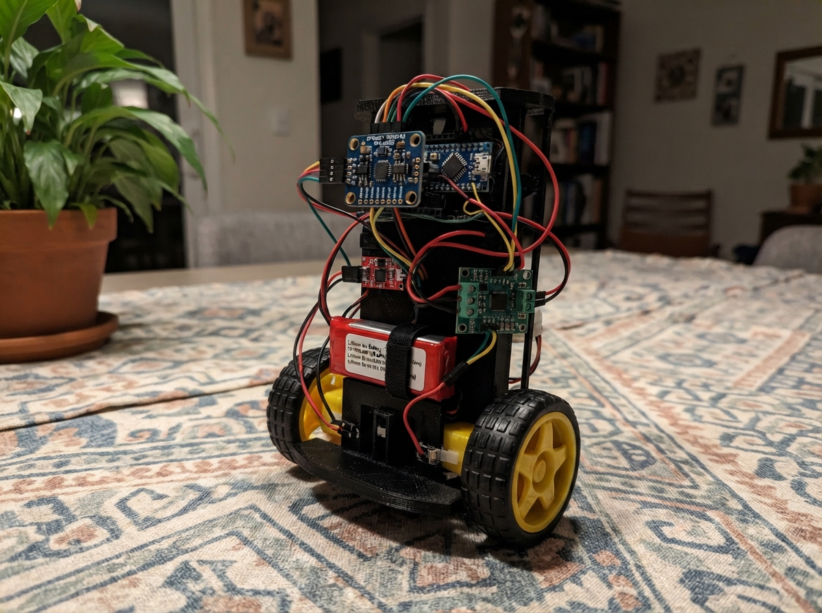
This self-balancing robot uses an ESP32 microcontroller and a 6-axis IMU sensor to maintain upright equilibrium on two motorized wheels. By continuously reading pitch angle from the MPU-6050 and adjusting motor speed through a dual motor driver, the robot actively corrects its tilt to stay balanced. The guide provides a complete parts list, wiring diagram, and step-by-step assembly instructions to build a functioning two-wheeled balancer from scratch.
The firmware implements a proportional-derivative (PD) control loop that processes gyroscope and accelerometer data to calculate real-time motor commands. Builders will learn how to calibrate the sensor, tune control parameters safely, and perform initial balance tests with the wheels off the ground before running the completed robot.
Wiring diagram

Gather all the parts
Assemble it in 7 steps
1. Build the wheel base
Fit left_motor_1 and right_motor_1 to opposite sides of a rigid two-wheel chassis, with both wheel axles on one straight line. Attach the wheels and leave enough room above the axle for the ESP32 and battery.
- Keep the chassis as light as possible and put the heavy battery near the axle; this makes balancing easier.
- Do not let motor wires rub on the wheels, because they can be pulled loose while the robot moves.
2. Mount the balance sensor
Fasten imu_1 flat and firmly to the chassis, centered left-to-right. Align its printed board front in the same forward direction as the robot; it must not wobble when the chassis tilts.
- Use foam tape only if it holds the board firmly; loose foam makes the sensor report the wrong lean angle.
- Do not mount the sensor at an angle or on a flexible wire bundle, because the robot cannot balance from a moving sensor.
3. Connect the sensor to the ESP32
With all power unplugged, connect imu_1 VIN to the ESP32 3V3 pin (power), imu_1 GND to ESP32 GND (ground), imu_1 SDA to GPIO21 (data), and imu_1 SCL to GPIO22 (clock).
- Use four short jumper wires and keep SDA and SCL away from the motor wires where possible.
- Make sure VIN and GND are not swapped — swapped power can damage the sensor.
4. Wire the motor driver
Connect motor_driver_1 GND to ESP32 GND (ground). Connect AIN1 to GPIO25 (left motor control), AIN2 to GPIO26 (left motor control), BIN1 to GPIO32 (right motor control), BIN2 to GPIO33 (right motor control), and nSLEEP to GPIO14 (driver enable). Connect left_motor_1 M1 to AOUT1 and M2 to AOUT2 (left wheel power). Connect right_motor_1 M1 to BOUT1 and M2 to BOUT2 (right wheel power).
- Use thicker wires for the four motor wires than for the small signal wires. Label the left and right motors before continuing.
- Do not connect either motor directly to the ESP32 pins — the motor current can damage the board.
5. Set the battery voltage converter
Connect battery_1 BAT+ to motor_regulator_1 VIN (battery power) and battery_1 BAT- to motor_regulator_1 GND (ground). Before connecting anything else, use a meter and turn the small adjustment screw until motor_regulator_1 VOUT measures exactly 5.0 V.
- Turn the adjustment screw very slowly and measure again after every small turn.
- Never connect the converter output to the robot before it is set to 5.0 V — a higher setting can damage the ESP32, sensor, and motors.
6. Connect the 5 V supply
After the converter is set to 5.0 V and power is unplugged, connect motor_regulator_1 VOUT to the ESP32 5V/VIN pin (power) and to motor_driver_1 VM (motor power). Keep the regulator GND, ESP32 GND, driver GND, sensor GND, and battery BAT- all connected together (shared ground).
- A shared ground is the common return wire that lets the ESP32 tell the motor driver what to do.
- Do not plug USB into the ESP32 while the 5 V converter is connected unless your board documentation says its 5 V input is protected against two power sources.
7. Do the first safe balance test
Raise the chassis so both wheels are clear of the table, then plug in the battery. Keep the robot upright and still for its first two seconds while it learns the sensor’s resting position. Only set it on the floor after you confirm both wheels try to correct a gentle forward and backward tilt.
- If one wheel corrects in the wrong direction, unplug the battery and swap that motor’s two wires at the driver output.
- Keep fingers, hair, and loose clothing away from the wheels, because the robot can spin them suddenly during testing.
Review all connections
1. Connections between "imu_1" and "ESP32"
2. Connections between "motor_driver_1" and "ESP32"
3. Connections between "battery_1" and "ESP32"
4. Connections between "motor_regulator_1" and "ESP32"
5. Connections between "left_motor_1" and "ESP32"
6. Connections between "right_motor_1" and "ESP32"
Deploy the firmware
#include <Arduino.h>
#include <Wire.h>
#include <MPU6050.h>


// Forward declarations
void setMotor(int speed, int channelForward, int channelReverse);
void stopMotors();
void driveBothMotors(int speed);
void calibrateGyro();

constexpr int MPU_SDA_PIN = 21;
constexpr int MPU_SCL_PIN = 22;
constexpr int LEFT_IN1_PIN = 25;
constexpr int LEFT_IN2_PIN = 26;
constexpr int RIGHT_IN1_PIN = 32;
constexpr int RIGHT_IN2_PIN = 33;
constexpr int DRIVER_SLEEP_PIN = 14;

constexpr int LEFT_PWM_A = 0;
constexpr int LEFT_PWM_B = 1;
constexpr int RIGHT_PWM_A = 2;
constexpr int RIGHT_PWM_B = 3;
constexpr int PWM_FREQUENCY = 20000;
constexpr int PWM_RESOLUTION = 8;
constexpr int MAX_PWM = 255;

// Tune these safely with the wheels off the floor.
constexpr float TARGET_ANGLE_DEG = 0.0f;
constexpr float KP = 20.0f;
constexpr float KD = 0.85f;
constexpr float FILTER_WEIGHT = 0.98f;
constexpr float FALL_ANGLE_DEG = 35.0f;
constexpr int MIN_DRIVE_PWM = 42;

MPU6050 mpu;
float gyroYOffset = 0.0f;
float pitchDeg = 0.0f;
unsigned long lastControlUs = 0;
bool sensorReady = false;

void setMotor(int speed, int channelForward, int channelReverse) {
  speed = constrain(speed, -MAX_PWM, MAX_PWM);
  if (speed > 0) {
    ledcWrite(channelForward, speed);
    ledcWrite(channelReverse, 0);
  } else if (speed < 0) {
    ledcWrite(channelForward, 0);
    ledcWrite(channelReverse, -speed);
  } else {
    ledcWrite(channelForward, 0);
    ledcWrite(channelReverse, 0);
  }
}

void stopMotors() {
  setMotor(0, LEFT_PWM_A, LEFT_PWM_B);
  setMotor(0, RIGHT_PWM_A, RIGHT_PWM_B);
}

void driveBothMotors(int speed) {
  if (speed != 0 && abs(speed) < MIN_DRIVE_PWM) {
    speed = speed > 0 ? MIN_DRIVE_PWM : -MIN_DRIVE_PWM;
  }
  setMotor(speed, LEFT_PWM_A, LEFT_PWM_B);
  setMotor(speed, RIGHT_PWM_A, RIGHT_PWM_B);
}

void calibrateGyro() {
  constexpr int SAMPLES = 800;
  long gyroSum = 0;
  for (int i = 0; i < SAMPLES; ++i) {
    int16_t gx, gy, gz;
    mpu.getRotation(&gx, &gy, &gz);
    gyroSum += gy;
    delay(2);
  }
  gyroYOffset = gyroSum / static_cast<float>(SAMPLES);
}

void setup() {
  Serial.begin(115200);
  Wire.begin(MPU_SDA_PIN, MPU_SCL_PIN);
  Wire.setClock(400000);

  pinMode(DRIVER_SLEEP_PIN, OUTPUT);
  digitalWrite(DRIVER_SLEEP_PIN, LOW);

  ledcSetup(LEFT_PWM_A, PWM_FREQUENCY, PWM_RESOLUTION);
  ledcSetup(LEFT_PWM_B, PWM_FREQUENCY, PWM_RESOLUTION);
  ledcSetup(RIGHT_PWM_A, PWM_FREQUENCY, PWM_RESOLUTION);
  ledcSetup(RIGHT_PWM_B, PWM_FREQUENCY, PWM_RESOLUTION);
  ledcAttachPin(LEFT_IN1_PIN, LEFT_PWM_A);
  ledcAttachPin(LEFT_IN2_PIN, LEFT_PWM_B);
  ledcAttachPin(RIGHT_IN1_PIN, RIGHT_PWM_A);
  ledcAttachPin(RIGHT_IN2_PIN, RIGHT_PWM_B);
  stopMotors();

  mpu.initialize();
  if (!mpu.testConnection()) {
    Serial.println("MPU-6050 not found: motors stay off.");
    return;
  }

  Serial.println("Hold robot upright and still: calibrating.");
  calibrateGyro();

  int16_t ax, ay, az;
  mpu.getAcceleration(&ax, &ay, &az);
  pitchDeg = atan2f(static_cast<float>(ax), static_cast<float>(az)) * 180.0f / PI;
  sensorReady = true;
  lastControlUs = micros();
  digitalWrite(DRIVER_SLEEP_PIN, HIGH);
  Serial.println("Balancing enabled.");
}

void loop() {
  if (!sensorReady) {
    digitalWrite(DRIVER_SLEEP_PIN, LOW);
    stopMotors();
    delay(100);
    return;
  }

  const unsigned long nowUs = micros();
  const float dt = (nowUs - lastControlUs) / 1000000.0f;
  if (dt < 0.004f) return;
  lastControlUs = nowUs;

  int16_t ax, ay, az, gx, gy, gz;
  mpu.getMotion6(&ax, &ay, &az, &gx, &gy, &gz);

  const float accelPitchDeg = atan2f(static_cast<float>(ax), static_cast<float>(az)) * 180.0f / PI;
  const float gyroRateDegPerSecond = (static_cast<float>(gy) - gyroYOffset) / 131.0f;
  pitchDeg = FILTER_WEIGHT * (pitchDeg + gyroRateDegPerSecond * dt) +
             (1.0f - FILTER_WEIGHT) * accelPitchDeg;

  if (fabsf(pitchDeg - TARGET_ANGLE_DEG) > FALL_ANGLE_DEG) {
    stopMotors();
    return;
  }

  const float error = pitchDeg - TARGET_ANGLE_DEG;
  const int command = static_cast<int>(KP * error + KD * gyroRateDegPerSecond);
  driveBothMotors(command);
}
Remix this project
Make it yours in one click
Open a full copy of this project in your own Schematik workspace — diagram, code, parts, and assembly steps included. Swap the sensor, add features, or redesign the whole thing with AI. The author's original stays untouched.
Related projects

Create A Complete Electrical Schematic Esp32 Sma
ESP32 · September 17, 2026Ayansh Agrawal
ESP32 Kare Ekran Projeleri
ESP32 · September 16, 2026Seref Ai
Component Qty --------------------------- ------
ESP32 · September 16, 2026Yathartha Chakrawal