Community project
Pico Pomodoro Timer
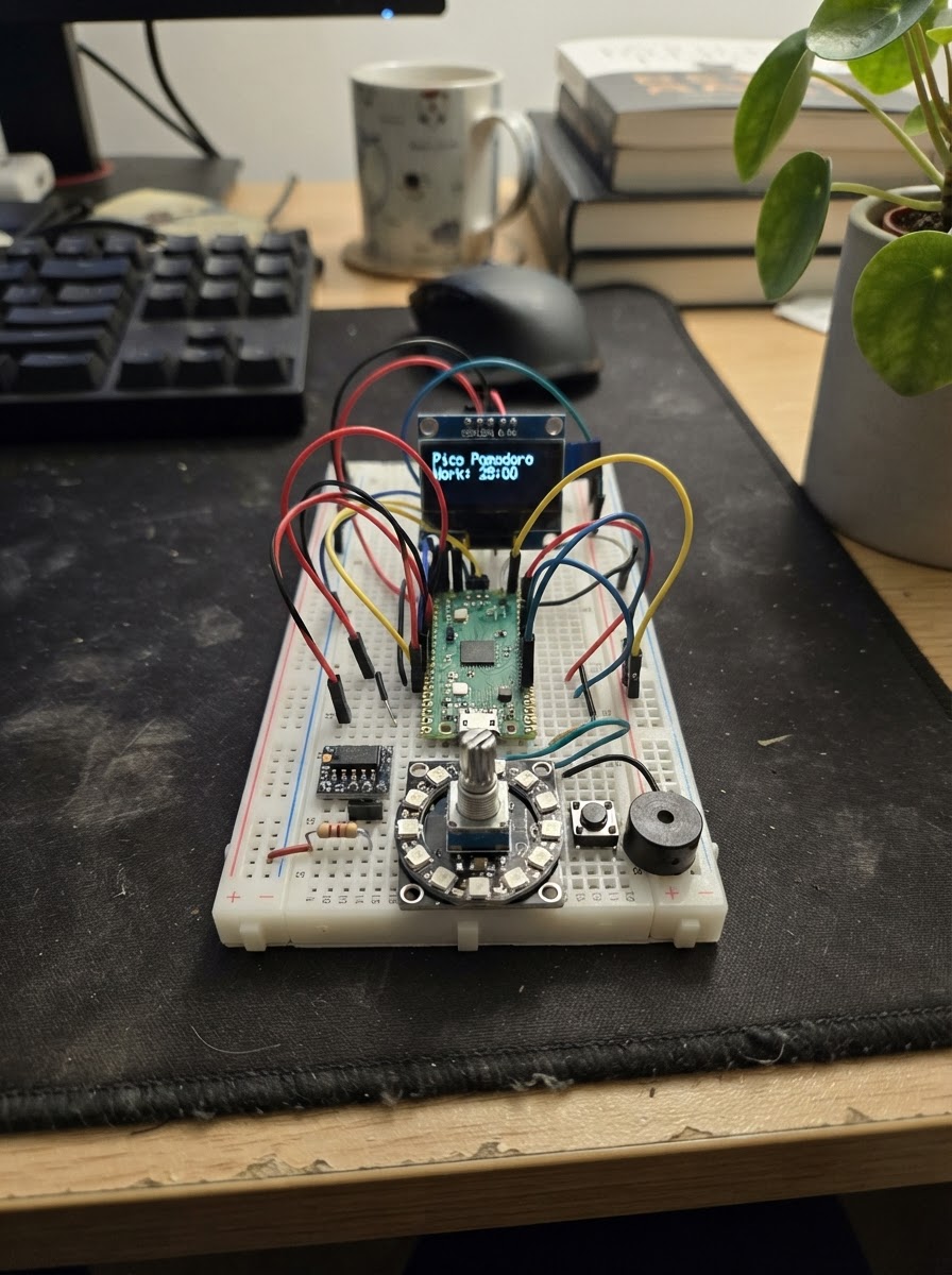
This guide builds a Pomodoro timer on a Raspberry Pi Pico with visual and audio feedback. The 128×64 OLED display shows the current phase and remaining time, while a 12-LED NeoPixel ring provides a glanceable progress indicator that changes color for focus, short break, and long break sessions. A rotary encoder adjusts session lengths, four buttons control playback and reset, and an active buzzer signals phase transitions.
The guide includes a complete wiring diagram showing how to safely integrate 3.3 V logic (OLED, encoder, buttons) and 5 V NeoPixels using a level shifter, a full parts list with recommended suppliers, Arduino-compatible firmware with debounced input handling and timer logic, and step-by-step assembly instructions with safety checks before powering on.
Wiring diagram

Gather all the parts
Assemble it in 7 steps
1. Keep the Pico unpowered while wiring
Unplug the Raspberry Pi Pico USB cable. Use the Pico 3V3(OUT) rail only for the OLED and encoder module. The USB VBUS/5V rail is used only for the NeoPixel ring, AHCT buffer, and capacitor.
- Make one common ground rail joining the Pico, OLED, encoder, buttons, buzzer, level shifter, ring, and capacitor.
- Use a USB supply/cable capable of at least 1 A; the firmware intentionally limits ring brightness, but startup faults and full-brightness test code can draw much more current.
- Never connect 5 V directly to any Pico GPIO, OLED I2C line, encoder output, or button input.
- Verify breadboard power rails are not split in the middle before connecting USB.
2. Wire the OLED and rotary encoder at 3.3 V
Connect oled_1 VCC to Pico 3V3(OUT), GND to GND, SDA to GP4, and SCL to GP5. Connect encoder_1 VCC to 3V3(OUT), GND to GND, CLK to GP6, DT to GP7, and SW to GP8.
- Most SSD1306 modules use I2C address 0x3C, which the firmware expects.
- Power the KY-040 encoder from 3.3 V, not 5 V, so its CLK/DT/SW outputs are safe for the Pico.
- If your OLED board is labelled 5 V only or has pull-ups permanently tied to 5 V, do not connect its I2C pins directly to the Pico. Use a 3.3 V-capable OLED module.
3. Wire the four active-low buttons
For button_start_1, button_reset_1, button_skip_1, and the encoder_1 push-button already wired in step 2, connect one switch terminal to the shared ground. Connect the other terminals to GP9 (start/pause button), GP10 (reset), and GP11 (skip). The encoder SW goes to GP8. The firmware enables internal pull-ups, so a press reads LOW.
- Tactile switches have internally common pairs of legs; use pins from opposite sides of the switch, not two legs on the same side.
- Keep button leads short. Firmware debounce is 30 ms; if a particularly noisy mechanical encoder still skips, add 10 nF capacitors from CLK and DT to ground near the encoder.
- Do not add external pull-ups to 5 V. All input pull-ups must remain at 3.3 V.
4. Wire the active buzzer
Connect buzzer_1 GND to the shared ground and SIGNAL to GP12. Use a 3.3 V active buzzer module; it produces its own tone whenever GP12 is HIGH.
- If the buzzer is very loud, cover its sound port partly with tape rather than adding a resistor in its ground line.
- A bare high-current buzzer is not the same as a 3.3 V active buzzer module and may need a transistor driver; do not connect one directly to GP12.
5. Build the protected 5 V NeoPixel data path
Connect levelshifter_1 VCC to USB 5 V (VBUS) and GND to common ground. Tie 1OE to ground to enable channel 1. Connect Pico GP13 to 1A. Connect 1Y to one end of data_resistor_1; connect the other resistor end to ring_1 DATA_IN. Tie 2OE, 3OE, and 4OE to 5 V so unused AHCT outputs are disabled. Leave the unused buffer inputs and outputs unconnected.
- For a bare 74AHCT125 DIP package, use its datasheet pin numbers; the signal labels in the wiring diagram describe its logical pins.
- Place the 330 ohm resistor close to the ring DATA_IN pad and keep the data wire short.
- The AHCT125 must run from 5 V. It converts the Pico’s 3.3 V data signal into a reliable 5 V WS2812 signal; do not omit it when the ring is powered at 5 V.
6. Connect and protect the NeoPixel 5 V supply
Connect ring_1 VCC to USB 5 V (VBUS) and ring_1 GND to common ground. Install bulk_capacitor_1 directly across the ring supply: P1/positive to 5 V and P2/negative/striped lead to ground. Leave DATA_OUT unconnected.
- Put the capacitor physically close to the ring power pads.
- The ring’s 5 V and the Pico’s ground must share a common ground for data to work.
- Observe the capacitor polarity exactly: its striped negative lead goes to GND. Reversing an electrolytic capacitor can cause it to fail dangerously.
- Do not power the ring from the Pico 3V3(OUT) pin.
7. Inspect before USB power
Check every 5 V lead is limited to the NeoPixel ring, AHCT125 VCC, capacitor positive lead, and the board’s VBUS distribution. Confirm no 5 V line touches GP4–GP13. Then connect the Pico by USB and use Schematik’s Deploy button to load the firmware.
- On first power-up, the display should show FOCUS and 25:00. Either the encoder push-button or the separate start/pause button starts the timer.
- Turn the encoder only while paused to adjust the currently selected period in one-minute steps; reset restores the period’s configured time and skip advances phase.
- If anything becomes hot, disconnect USB immediately and re-check the 5 V, ground, capacitor polarity, and level-shifter wiring.
Review all connections
1. Connections between "oled_1" and "Raspberry Pi Pico"
2. Connections between "encoder_1" and "Raspberry Pi Pico"
3. Connections between "button_start_1" and "Raspberry Pi Pico"
4. Connections between "button_reset_1" and "Raspberry Pi Pico"
5. Connections between "button_skip_1" and "Raspberry Pi Pico"
6. Connections between "buzzer_1" and "Raspberry Pi Pico"
7. Connections between "levelshifter_1" and "Raspberry Pi Pico"
8. Connections between "data_resistor_1" and "Raspberry Pi Pico"
9. Connections between "ring_1" and "Raspberry Pi Pico"
10. Connections between "bulk_capacitor_1" and "Raspberry Pi Pico"
Deploy the firmware
#include <Arduino.h>
#include <Wire.h>
#include <Adafruit_GFX.h>
#include <Adafruit_SSD1306.h>
#include <Adafruit_NeoPixel.h>


// Hoisted type definitions
enum TimerPhase { FOCUS, SHORT_BREAK, LONG_BREAK };

struct DebouncedButton {
  uint8_t pin;
  bool stableState;
  bool previousStableState;
  bool rawState;
  uint32_t changedAt;
};


// Forward declarations
void setBuzzer(bool on);
void queueBeeps(uint8_t count, uint32_t firstDelay);
void serviceBuzzer();
bool pressed(DebouncedButton &button);
void resetCurrentTimer();
void beginBreak();
void beginFocus();
void finishPhase();
void handleEncoder();
void handleInputs();
uint32_t scaleColor(uint8_t r, uint8_t g, uint8_t b, uint8_t level);
void updateRing();
void drawDisplay();
void serviceTimer();

constexpr uint8_t OLED_SDA_PIN = 4;
constexpr uint8_t OLED_SCL_PIN = 5;
constexpr uint8_t ENCODER_CLK_PIN = 6;
constexpr uint8_t ENCODER_DT_PIN = 7;
constexpr uint8_t ENCODER_SW_PIN = 8;
constexpr uint8_t START_BUTTON_PIN = 9;
constexpr uint8_t RESET_BUTTON_PIN = 10;
constexpr uint8_t SKIP_BUTTON_PIN = 11;
constexpr uint8_t BUZZER_PIN = 12;
constexpr uint8_t NEOPIXEL_PIN = 13;

constexpr uint8_t SCREEN_WIDTH = 128;
constexpr uint8_t SCREEN_HEIGHT = 64;
constexpr uint8_t PIXEL_COUNT = 12;
constexpr uint32_t FOCUS_SECONDS = 25UL * 60UL;
constexpr uint32_t SHORT_BREAK_SECONDS = 5UL * 60UL;
constexpr uint32_t LONG_BREAK_SECONDS = 15UL * 60UL;
constexpr uint32_t LAST_FIVE_MINUTES = 5UL * 60UL;
constexpr uint32_t LAST_TEN_SECONDS = 10UL;
constexpr uint32_t DEBOUNCE_MS = 30;
constexpr uint32_t RING_FRAME_MS = 50;
constexpr uint32_t BEEP_TICK_MS = 70;

Adafruit_SSD1306 display(SCREEN_WIDTH, SCREEN_HEIGHT, &Wire, -1);
Adafruit_NeoPixel ring(PIXEL_COUNT, NEOPIXEL_PIN, NEO_GRB + NEO_KHZ800);


TimerPhase phase = FOCUS;
bool running = false;
uint8_t completedFocusCycles = 0;
uint32_t configuredSeconds = FOCUS_SECONDS;
uint32_t remainingSeconds = FOCUS_SECONDS;
uint32_t lastSecondMs = 0;
uint32_t lastRingMs = 0;
uint32_t lastTickSecond = 0xFFFFFFFFUL;
bool displayDirty = true;


DebouncedButton encoderButton{ENCODER_SW_PIN, HIGH, HIGH, HIGH, 0};
DebouncedButton startButton{START_BUTTON_PIN, HIGH, HIGH, HIGH, 0};
DebouncedButton resetButton{RESET_BUTTON_PIN, HIGH, HIGH, HIGH, 0};
DebouncedButton skipButton{SKIP_BUTTON_PIN, HIGH, HIGH, HIGH, 0};

int lastEncoderClk = HIGH;
uint32_t buzzerOffAt = 0;
uint8_t queuedBeeps = 0;
uint8_t beepsStarted = 0;
bool buzzerOn = false;
uint32_t nextBeepAt = 0;

const char *phaseName() {
  if (phase == FOCUS) return "FOCUS";
  if (phase == SHORT_BREAK) return "SHORT BREAK";
  return "LONG BREAK";
}

void setBuzzer(bool on) {
  digitalWrite(BUZZER_PIN, on ? HIGH : LOW);
  buzzerOn = on;
}

void queueBeeps(uint8_t count, uint32_t firstDelay = 0) {
  queuedBeeps = count;
  beepsStarted = 0;
  nextBeepAt = millis() + firstDelay;
}

void serviceBuzzer() {
  uint32_t now = millis();
  if (buzzerOn && (int32_t)(now - buzzerOffAt) >= 0) {
    setBuzzer(false);
    if (beepsStarted < queuedBeeps) nextBeepAt = now + 120;
  }
  if (!buzzerOn && beepsStarted < queuedBeeps && (int32_t)(now - nextBeepAt) >= 0) {
    setBuzzer(true);
    ++beepsStarted;
    buzzerOffAt = now + ((queuedBeeps == 1) ? 700 : 160);
  }
}

bool pressed(DebouncedButton &button) {
  bool reading = digitalRead(button.pin);
  uint32_t now = millis();
  if (reading != button.rawState) {
    button.rawState = reading;
    button.changedAt = now;
  }
  if ((now - button.changedAt) >= DEBOUNCE_MS && button.stableState != button.rawState) {
    button.previousStableState = button.stableState;
    button.stableState = button.rawState;
    return button.previousStableState == HIGH && button.stableState == LOW;
  }
  return false;
}

void resetCurrentTimer() {
  running = false;
  remainingSeconds = configuredSeconds;
  lastTickSecond = 0xFFFFFFFFUL;
  displayDirty = true;
}

void beginBreak() {
  if (completedFocusCycles >= 4) {
    phase = LONG_BREAK;
    configuredSeconds = LONG_BREAK_SECONDS;
  } else {
    phase = SHORT_BREAK;
    configuredSeconds = SHORT_BREAK_SECONDS;
  }
  remainingSeconds = configuredSeconds;
  running = false;
  lastTickSecond = 0xFFFFFFFFUL;
  queueBeeps(1);
  displayDirty = true;
}

void beginFocus() {
  phase = FOCUS;
  configuredSeconds = FOCUS_SECONDS;
  remainingSeconds = configuredSeconds;
  running = false;
  lastTickSecond = 0xFFFFFFFFUL;
  queueBeeps(2);
  displayDirty = true;
}

void finishPhase() {
  if (phase == FOCUS) {
    if (completedFocusCycles < 4) ++completedFocusCycles;
    beginBreak();
  } else {
    if (phase == LONG_BREAK) completedFocusCycles = 0;
    beginFocus();
  }
}

void handleEncoder() {
  int clk = digitalRead(ENCODER_CLK_PIN);
  if (clk != lastEncoderClk && clk == LOW && !running) {
    int direction = (digitalRead(ENCODER_DT_PIN) != clk) ? 1 : -1;
    int32_t adjusted = (int32_t)remainingSeconds + direction * 60;
    if (adjusted < 60) adjusted = 60;
    if (adjusted > 99 * 60) adjusted = 99 * 60;
    remainingSeconds = (uint32_t)adjusted;
    configuredSeconds = remainingSeconds;
    displayDirty = true;
  }
  lastEncoderClk = clk;
}

void handleInputs() {
  handleEncoder();
  if (pressed(encoderButton) || pressed(startButton)) {
    running = !running;
    lastSecondMs = millis();
    displayDirty = true;
  }
  if (pressed(resetButton)) resetCurrentTimer();
  if (pressed(skipButton)) finishPhase();
}

uint32_t scaleColor(uint8_t r, uint8_t g, uint8_t b, uint8_t level) {
  return ring.Color((uint16_t)r * level / 255, (uint16_t)g * level / 255, (uint16_t)b * level / 255);
}

void updateRing() {
  uint32_t now = millis();
  if (now - lastRingMs < RING_FRAME_MS) return;
  lastRingMs = now;

  float wave = (sinf((float)now * 0.005f) + 1.0f) * 0.5f;
  uint8_t brightness = 0;
  uint8_t r = 0, g = 0, b = 0;

  if (phase == FOCUS) {
    if (remainingSeconds == 0) {
      r = 0; g = 180; b = 20; brightness = 180;
    } else {
      r = 25; g = 80; b = 220;
      uint8_t floorLevel = 20;
      uint8_t ceilingLevel = 90;
      if (remainingSeconds <= LAST_FIVE_MINUTES) {
        float urgency = 1.0f - (float)remainingSeconds / LAST_FIVE_MINUTES;
        floorLevel = 30 + (uint8_t)(urgency * 55.0f);
        ceilingLevel = 115 + (uint8_t)(urgency * 120.0f);
        r = 180; g = 35; b = 20;
      }
      brightness = floorLevel + (uint8_t)((ceilingLevel - floorLevel) * wave);
      if (!running) brightness = 18;
    }
  } else {
    r = 210; g = 130; b = 0;
    brightness = running ? (35 + (uint8_t)(125 * wave)) : 18;
  }

  for (uint8_t i = 0; i < PIXEL_COUNT; ++i) ring.setPixelColor(i, scaleColor(r, g, b, brightness));
  ring.show();
}

void drawDisplay() {
  display.clearDisplay();
  display.setTextColor(SSD1306_WHITE);
  display.setTextSize(1);
  display.setCursor(0, 0);
  display.print(phaseName());
  display.setCursor(92, 0);
  display.print(running ? "RUN" : "PAUSE");

  uint32_t minutes = remainingSeconds / 60;
  uint32_t seconds = remainingSeconds % 60;
  char timeBuffer[8];
  snprintf(timeBuffer, sizeof(timeBuffer), "%02lu:%02lu", (unsigned long)minutes, (unsigned long)seconds);
  display.setTextSize(3);
  display.setCursor(18, 15);
  display.print(timeBuffer);

  display.setTextSize(1);
  display.setCursor(0, 45);
  display.print("Focus cycles: ");
  display.print(completedFocusCycles);
  display.print("/4");

  display.drawRect(0, 55, 128, 9, SSD1306_WHITE);
  uint32_t elapsed = configuredSeconds > remainingSeconds ? configuredSeconds - remainingSeconds : 0;
  uint8_t fill = configuredSeconds ? (uint32_t)126 * elapsed / configuredSeconds : 0;
  if (fill > 0) display.fillRect(1, 56, fill, 7, SSD1306_WHITE);
  display.display();
  displayDirty = false;
}

void serviceTimer() {
  if (!running) return;
  uint32_t now = millis();
  while (now - lastSecondMs >= 1000 && running) {
    lastSecondMs += 1000;
    if (remainingSeconds > 0) --remainingSeconds;
    displayDirty = true;
    if (remainingSeconds <= LAST_TEN_SECONDS && remainingSeconds > 0 && remainingSeconds != lastTickSecond) {
      lastTickSecond = remainingSeconds;
      queueBeeps(1);
    }
    if (remainingSeconds == 0) finishPhase();
  }
}

void setup() {
  pinMode(ENCODER_CLK_PIN, INPUT_PULLUP);
  pinMode(ENCODER_DT_PIN, INPUT_PULLUP);
  pinMode(ENCODER_SW_PIN, INPUT_PULLUP);
  pinMode(START_BUTTON_PIN, INPUT_PULLUP);
  pinMode(RESET_BUTTON_PIN, INPUT_PULLUP);
  pinMode(SKIP_BUTTON_PIN, INPUT_PULLUP);
  pinMode(BUZZER_PIN, OUTPUT);
  setBuzzer(false);
  lastEncoderClk = digitalRead(ENCODER_CLK_PIN);
Wire.begin();
  display.begin(SSD1306_SWITCHCAPVCC, 0x3C);
  display.clearDisplay();
  display.display();

  ring.begin();
  ring.setBrightness(255);
  ring.clear();
  ring.show();
  lastSecondMs = millis();
}

void loop() {
  handleInputs();
  serviceTimer();
  serviceBuzzer();
  updateRing();
  if (displayDirty) drawDisplay();
}
Remix this project
Make it yours in one click
Open a full copy of this project in your own Schematik workspace — diagram, code, parts, and assembly steps included. Swap the sensor, add features, or redesign the whole thing with AI. The author's original stays untouched.
Related projects
Drone Light Safety Controller (copy)
Raspberry Pi Pico · September 26, 2026ianlex.wip
RGB Button Color Controller
Raspberry Pi Pico · September 25, 2026juliaccquintanilha
Zaprojektuj Emulator Rom Dla Zx Spectrum Harlequ
Raspberry Pi Pico · September 25, 2026Piotr Chmielecki