Community project
Portable E-Ink Weather Monitor
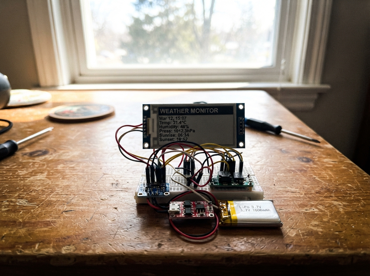
This portable weather monitor displays real-time temperature, humidity, and pressure readings on a low-power e-ink screen. Built around an ESP32 microcontroller, BME280 environmental sensor, and Waveshare 2.9-inch e-ink display, the device runs for weeks on a single charge thanks to the display's minimal power consumption and efficient firmware that updates readings every five minutes.
The guide provides a complete parts list, wiring diagram showing all sensor and display connections, step-by-step assembly instructions, and ready-to-upload Arduino firmware. Builders will learn how to integrate I2C and SPI protocols, manage battery charging safely with the TP4056 module, and optimize display updates to maximize runtime on the included 1000mAh LiPo battery.
Wiring diagram

Gather all the parts
Assemble it in 4 steps
1. Place the ESP32 and the sensor
Put the ESP32 DevKit V1 and bme280_1 on a breadboard or non-metal work surface. Connect BME280 VCC to ESP32 3V3 (power), BME280 GND to ESP32 GND (ground), BME280 SDA to GPIO21 (data), and BME280 SCL to GPIO22 (clock).
- The BME280 board normally has the pin names printed beside its header. Keep its small vent opening clear so it can sense the surrounding air.
- Make sure VCC and GND are not swapped — swapped power can damage the sensor.
2. Wire the e-paper screen
Connect epaper_1 VCC to ESP32 3V3 (power), epaper_1 GND to ESP32 GND (ground), DIN to GPIO23 (screen data), CLK to GPIO18 (screen clock), CS to GPIO4 (screen select), DC to GPIO27 (screen command/data), RST to GPIO26 (screen reset), and BUSY to GPIO25 (screen ready signal).
- Use short jumper wires for the display. Match the labels printed on the display board, not the order of the pins in a product photo.
- Power the e-paper display from 3V3, not 5V — 5V signal or supply wiring can damage a 3.3V display module.
3. Connect the rechargeable battery safely
With all USB cables unplugged, connect battery_1 +V to charger_1 B+ (battery positive) and battery_1 GND to charger_1 B- (battery negative). Connect charger_1 OUT+ to boost_5v_1 VIN (protected battery power) and charger_1 OUT- to boost_5v_1 GND (ground). Connect boost_5v_1 VOUT to ESP32 VIN (5V power) and boost_5v_1 GND to ESP32 GND (ground).
- Use a LiPo battery with its own protected connector if possible. The charger board's USB socket is only for charging the battery.
- Never connect the LiPo battery leads backwards — that can overheat or permanently damage the battery, charger, or wiring.
- Do not charge a swollen, torn, or hot battery, and do not leave a charging battery unattended.
4. Do a final power check
Before connecting the battery, look at every power wire again: all GND wires must meet at ESP32 GND, the boost module's 5V output goes only to ESP32 VIN, and the BME280 and epaper_1 both receive ESP32 3V3 (power). Then plug the ESP32 into USB for its first test.
- For the first test, leave the battery disconnected and power only the ESP32 by USB. This makes it easier to find a misplaced wire safely.
- Do not plug USB into the ESP32 while an unknown or untested boost module is also feeding VIN — incorrect regulator wiring can damage the board or computer USB port.
Review all connections
1. Connections between "bme280_1" and "ESP32"
2. Connections between "epaper_1" and "ESP32"
3. Connections between "battery_1" and "ESP32"
4. Connections between "charger_1" and "ESP32"
5. Connections between "boost_5v_1" and "ESP32"
Deploy the firmware
#include <Arduino.h>
#include <Wire.h>
#include <SPI.h>
#include <Adafruit_BME280.h>
#include <GxEPD2_BW.h>
#include <GxEPD2_290_T5.h>
#include <Fonts/FreeMonoBold9pt7b.h>
#include <Fonts/FreeMonoBold12pt7b.h>


// Forward declarations
void drawHeader();
void drawReadings();
void fullScreenDraw();
void partialReadingsDraw();

constexpr int BME_SDA_PIN = 21;
constexpr int BME_SCL_PIN = 22;
constexpr int EPD_SCK_PIN = 18;
constexpr int EPD_MOSI_PIN = 23;
constexpr int EPD_CS_PIN = 4;
constexpr int EPD_DC_PIN = 27;
constexpr int EPD_RST_PIN = 26;
constexpr int EPD_BUSY_PIN = 25;
constexpr uint32_t UPDATE_INTERVAL_MS = 300000UL;

Adafruit_BME280 bme;
GxEPD2_BW<GxEPD2_290_T5, GxEPD2_290_T5::HEIGHT> display(
  GxEPD2_290_T5(EPD_CS_PIN, EPD_DC_PIN, EPD_RST_PIN, EPD_BUSY_PIN)
);

bool sensorReady = false;
uint32_t lastUpdateMs = 0;

void drawHeader()
{
  display.setTextColor(GxEPD_BLACK);
  display.setFont(&FreeMonoBold12pt7b);
  display.setCursor(8, 20);
  display.print("ENVIRONMENT");
  display.drawLine(6, 28, display.width() - 6, 28, GxEPD_BLACK);
}

void drawReadings()
{
  display.fillRect(0, 34, display.width(), display.height() - 34, GxEPD_WHITE);
  display.setTextColor(GxEPD_BLACK);

  if (!sensorReady)
  {
    display.setFont(&FreeMonoBold9pt7b);
    display.setCursor(8, 62);
    display.print("BME280 NOT FOUND");
    display.setCursor(8, 86);
    display.print("Check SDA/SCL wiring");
    return;
  }

  const float temperatureC = bme.readTemperature();
  const float humidity = bme.readHumidity();
  const float pressureHpa = bme.readPressure() / 100.0F;

  display.setFont(&FreeMonoBold9pt7b);
  display.setCursor(8, 54);
  display.printf("Temp: %5.1f C", temperatureC);
  display.setCursor(8, 80);
  display.printf("Hum : %5.1f %%", humidity);
  display.setCursor(8, 106);
  display.printf("Press: %4.0f hPa", pressureHpa);
}

void fullScreenDraw()
{
  display.setFullWindow();
  display.firstPage();
  do
  {
    display.fillScreen(GxEPD_WHITE);
    drawHeader();
    drawReadings();
  }
  while (display.nextPage());
}

void partialReadingsDraw()
{
  display.setPartialWindow(0, 32, display.width(), display.height() - 32);
  display.firstPage();
  do
  {
    drawReadings();
  }
  while (display.nextPage());
}

void setup()
{
  Serial.begin(115200);
  Wire.begin(BME_SDA_PIN, BME_SCL_PIN);
  sensorReady = bme.begin(0x77);

  SPI.begin(EPD_SCK_PIN, -1, EPD_MOSI_PIN, EPD_CS_PIN);
  display.init(115200, true, 2, false);
  display.setRotation(1);
  fullScreenDraw();
  lastUpdateMs = millis();
}

void loop()
{
  const uint32_t now = millis();
  if (now - lastUpdateMs >= UPDATE_INTERVAL_MS)
  {
    sensorReady = bme.begin(0x77);
    partialReadingsDraw();
    lastUpdateMs = now;
  }
}
Remix this project
Make it yours in one click
Open a full copy of this project in your own Schematik workspace — diagram, code, parts, and assembly steps included. Swap the sensor, add features, or redesign the whole thing with AI. The author's original stays untouched.