Community project
温湿度监测器
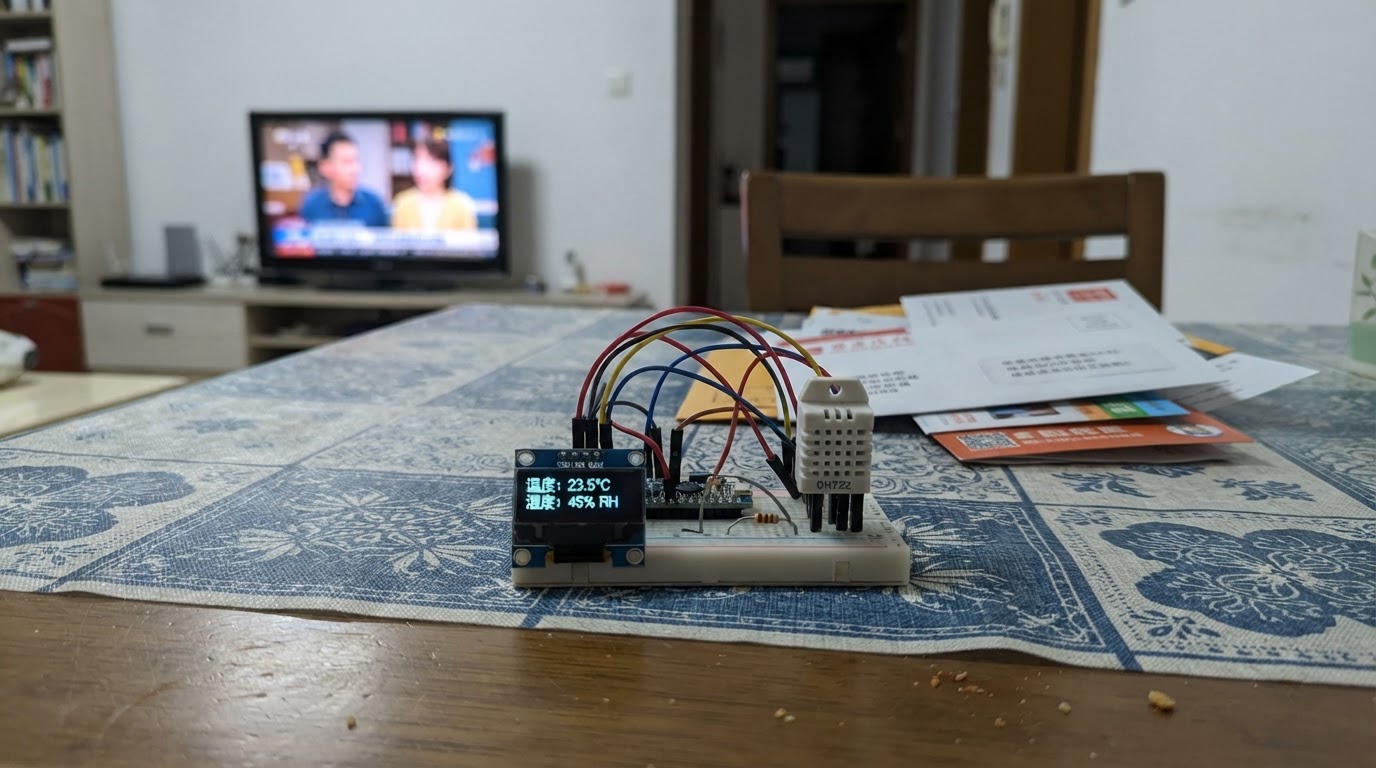
This project builds a temperature and humidity monitor using an ESP32 microcontroller, a DHT22 sensor, and an SSD1306 OLED display. The device reads ambient conditions every 2.5 seconds and shows real-time temperature in Celsius and relative humidity percentage on the small screen.
The guide provides a complete wiring diagram showing how to connect the OLED display via I2C (GPIO 21 and 22), wire the DHT22 sensor to GPIO 4 with a pull-up resistor, and assemble everything on a breadboard. Included are the full parts list, step-by-step assembly instructions, and ready-to-upload firmware with error detection that displays connection diagnostics if the sensor fails.
Wiring diagram

Gather all the parts
Assemble it in 4 steps
1. 先断开 USB 电源
在插线前先把 ESP32 的 USB 线拔掉。把 ESP32、OLED、DHT22 和一只 10 kΩ 电阻放在面包板旁边,方便逐根检查连接。
- 电阻没有正负方向,两只脚可以互换。
- 不要在 USB 仍插着时随意移动电源线;碰错位置可能让模块短路或重新启动。
2. 连接 OLED 显示屏
把 OLED 的 VCC 接到 ESP32 的 3V3 针脚,把 GND 接到 GND 针脚;再把 SDA 接到 GPIO21,把 SCL 接到 GPIO22。OLED 会用这两根信号线把文字和数字显示出来。
- OLED 模块上通常直接印有 VCC、GND、SDA、SCL;请按印字逐一接线。
- 确认 VCC 和 GND 没有接反;接反电源可能损坏显示屏。
3. 连接温湿度传感器和电阻
把 DHT22 的 VCC 接到 3V3,GND 接到 GND,DATA 接到 GPIO4。然后把 10 kΩ 电阻的一只脚接到 3V3,另一只脚接到同一条 DATA/GPIO4 线上;这只电阻让温湿度信号在空闲时保持稳定。
- 如果 DHT22 是裸的四脚传感器,正面对着你、通风栅格朝上时,脚通常从左到右是 VCC、DATA、未接、GND;仍应以你手上器件的印字或资料为准。
- 若是带三针小板的 DHT22,板上可能已经带了上拉电阻;保留外加的 10 kΩ 通常也可工作,但若读数不稳定可移除外加电阻再试。
- 不要把 DHT22 的 DATA 线直接接到 5V;ESP32 的信号针脚只能使用 3.3V 信号,5V 可能损坏它。
4. 最后检查并通电
检查所有模块的 GND 都回到 ESP32 的 GND,所有 VCC 都接到 3V3,且 DATA 只接 GPIO4。确认无误后用 USB 线连接 ESP32;程序会先显示启动提示,随后显示温度和湿度。
- 把线按颜色区分会更容易检查:红色接 3V3,黑色接 GND,其余颜色接 SDA、SCL 和 DATA。
- 在通电前再次确认 3V3 和 GND 没有被同一根跳线直接连在一起;这种短路可能让 USB 供电保护断开。
Review all connections
1. Connections between "oled_1" and "ESP32"
2. Connections between "dht22_1" and "ESP32"
3. Connections between "r_pullup_1" and "ESP32"
Deploy the firmware
#include <Arduino.h>
#include <Wire.h>
#include <Adafruit_GFX.h>
#include <Adafruit_SSD1306.h>
#include <DHT.h>
#include <math.h>

void drawReadings(float temperature, float humidity);
void drawSensorError();

constexpr int DHT_PIN = 4;
constexpr int OLED_SDA_PIN = 21;
constexpr int OLED_SCL_PIN = 22;
constexpr uint8_t DHT_TYPE = DHT22;
constexpr uint8_t SCREEN_WIDTH = 128;
constexpr uint8_t SCREEN_HEIGHT = 64;
constexpr unsigned long READ_INTERVAL_MS = 2500;

Adafruit_SSD1306 display(SCREEN_WIDTH, SCREEN_HEIGHT, &Wire, -1);
DHT dht(DHT_PIN, DHT_TYPE);

float lastTemperature = NAN;
float lastHumidity = NAN;
unsigned long lastReadMs = 0;
bool sensorErrorShown = false;

void drawReadings(float temperature, float humidity) {
  display.clearDisplay();
  display.setTextColor(SSD1306_WHITE);
  display.setTextSize(1);
  display.setCursor(0, 0);
  display.println(F("TEMP & HUMIDITY"));
  display.drawFastHLine(0, 11, SCREEN_WIDTH, SSD1306_WHITE);
  display.setTextSize(2);
  display.setCursor(0, 19);
  display.print(temperature, 1);
  display.println(F(" C"));
  display.setCursor(0, 43);
  display.print(humidity, 1);
  display.println(F(" %"));
  display.display();
}

void drawSensorError() {
  display.clearDisplay();
  display.setTextColor(SSD1306_WHITE);
  display.setTextSize(1);
  display.setCursor(0, 0);
  display.println(F("DHT22 not found"));
  display.println();
  display.println(F("Check VCC, GND"));
  display.println(F("and DATA to GPIO4"));
  display.display();
}

void setup() {
  Wire.begin(OLED_SDA_PIN, OLED_SCL_PIN);
  if (!display.begin(SSD1306_SWITCHCAPVCC, 0x3C)) {
    for (;;) delay(1000);
  }
  dht.begin();
  display.clearDisplay();
  display.setTextColor(SSD1306_WHITE);
  display.setTextSize(1);
  display.setCursor(0, 24);
  display.println(F("Starting monitor..."));
  display.display();
}

void loop() {
  const unsigned long now = millis();
  if (now - lastReadMs < READ_INTERVAL_MS) return;
  lastReadMs = now;

  const float humidity = dht.readHumidity();
  const float temperature = dht.readTemperature();
  if (isnan(humidity) || isnan(temperature)) {
    if (!sensorErrorShown) {
      drawSensorError();
      sensorErrorShown = true;
    }
    return;
  }

  const bool changed = sensorErrorShown || isnan(lastTemperature) ||
                       fabsf(temperature - lastTemperature) >= 0.1f ||
                       fabsf(humidity - lastHumidity) >= 0.1f;
  if (changed) {
    drawReadings(temperature, humidity);
    lastTemperature = temperature;
    lastHumidity = humidity;
    sensorErrorShown = false;
  }
}
Remix this project
Make it yours in one click
Open a full copy of this project in your own Schematik workspace — diagram, code, parts, and assembly steps included. Swap the sensor, add features, or redesign the whole thing with AI. The author's original stays untouched.