Community project
Protected 2S Motor Power Supply
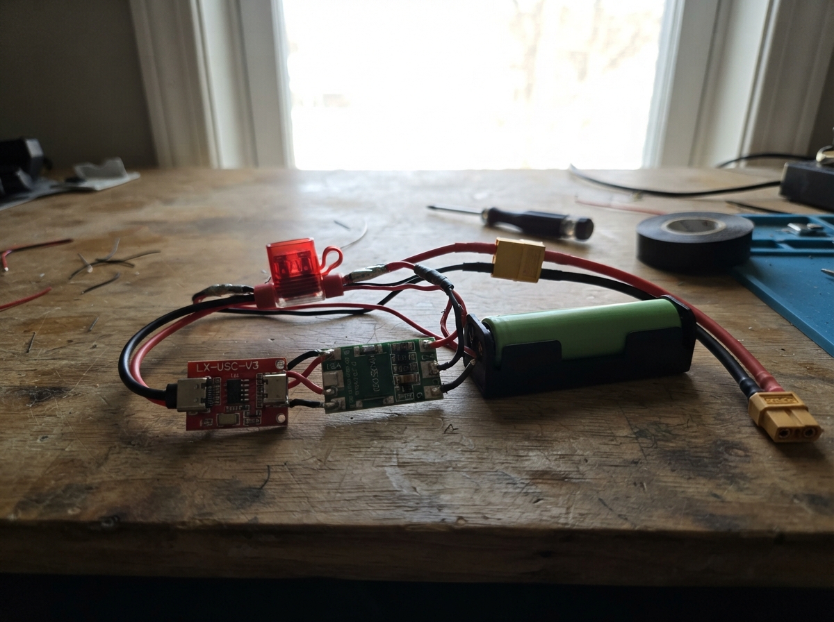
This project builds a protected external power supply for Motor 2040 using two 18650 lithium-ion cells in series. A 2S battery management system (BMS) protects against overcharge, over-discharge, and short circuits, while a USB-C charger and inline fuse provide additional safety layers. The result is a robust 7.4 V power source that can deliver up to 15 A continuously.
This guide provides a complete parts list, wiring diagram, and step-by-step assembly instructions. Since the protection hardware operates independently, no firmware configuration is needed—just verify voltages at each stage before connecting to Motor 2040. Builders will learn how to safely assemble lithium-ion battery packs with integrated protection and charging.
Wiring diagram

Gather all the parts
Assemble it in 5 steps
1. Prepare the two matching battery cells
Use two new, matching unprotected 18650 cells in a proper two-cell series holder or a professionally spot-welded battery pack. Put cell_1 and cell_2 in series: cell_1 POSITIVE joins cell_2 NEGATIVE. The remaining cell_1 NEGATIVE end is pack negative, and the remaining cell_2 POSITIVE end is pack positive.
- Use cells from the same maker and model, bought together, and charge them to nearly the same voltage before connecting them.
- A holder with nickel tabs or a ready-made 2S pack is much safer than loose cells.
- Do not solder directly onto loose 18650 cells; heat can damage a cell and create a fire risk.
- Never use damaged, dented, swollen, or mismatched cells.
2. Wire the protection board to the cells
With the cells removed from the holder, connect cell_1 NEGATIVE to bms_2s B−, the join between cell_1 POSITIVE and cell_2 NEGATIVE to bms_2s BM, and cell_2 POSITIVE to bms_2s B+. These three wires let the protection board watch both cells separately.
- Connect in this order: B− first, then BM, then B+.
- Use wire thick enough for your motors; 18 AWG silicone wire is a good starting point for the main positive and negative leads.
- Putting the BM wire on the wrong cell connection can destroy the BMS.
- Do not place the cells in the holder until you have checked the wiring with a multimeter.
3. Connect your LX-USC-V3 charging board
Leave the LX-USC-V3 set for 2S charging: the 3S solder link must stay open. Connect lx_usc_v3 B+ to bms_2s B+, lx_usc_v3 BM to bms_2s BM, and lx_usc_v3 B− to bms_2s C−. Plug a normal 5 V USB-C wall power supply into the LX-USC-V3 USB-C socket when charging.
- The BM pad on the charger is the middle connection marked BM on the photo; it goes to the same middle cell join as the BMS BM pad.
- Mount the charger where its USB-C socket remains easy to reach.
- Do not bridge the board’s 3S-setting pads: three cells would charge to 12.6 V, which is unsafe for this two-cell pack and exceeds the Motor 2040 motor-input limit.
- Do not charge the pack unattended or on carpet, bedding, or another flammable surface.
4. Add the fused Motor 2040 power lead
Connect bms_2s P+ to fuse_5a IN, then connect fuse_5a OUT to the Motor 2040 EXT PWR positive pad. Connect bms_2s P− to a Motor 2040 GND pad. P+ and P− are the protected output, so do not power the Motor 2040 from the BMS B+ or B− pads.
- Place the fuse holder close to the battery pack’s positive wire so most of the cable is protected.
- Use red wire for P+ and black wire for P−, then insulate every exposed joint with heat-shrink tubing.
- Reversing EXT PWR and GND can damage the Motor 2040.
- Make sure VCC and GND are not swapped before inserting the fuse or batteries.
5. Check voltages before powering the board
With the battery connected and the fuse fitted, measure between the Motor 2040 EXT PWR and GND pads. It must read roughly 6.0 V to 8.4 V, with EXT PWR positive. Only then connect it to the Motor 2040.
- A fully charged two-cell pack reads about 8.4 V; that is below the Motor 2040 10 V motor-input maximum.
- The BMS should turn the output off if there is a short or if a cell is discharged too far.
- On an unmodified Motor 2040, do not plug USB into a computer while this EXT PWR pack is connected; the board can back-power the USB connection.
- If the measured voltage is negative, zero, above 8.4 V, or not in the expected range, remove the batteries and recheck every connection before continuing.
Review all connections
1. Connections between "cell_1" and "Raspberry Pi Pico"
2. Connections between "cell_2" and "Raspberry Pi Pico"
3. Connections between "bms_2s" and "Raspberry Pi Pico"
4. Connections between "lx_usc_v3" and "Raspberry Pi Pico"
5. Connections between "fuse_5a" and "Raspberry Pi Pico"
Deploy the firmware
// This project is a protected external power supply for Motor 2040.
// The power hardware works independently of firmware.
void setup() {
}

void loop() {
}
Remix this project
Make it yours in one click
Open a full copy of this project in your own Schematik workspace — diagram, code, parts, and assembly steps included. Swap the sensor, add features, or redesign the whole thing with AI. The author's original stays untouched.