Community project
Protected Dual-Output Motor Supply
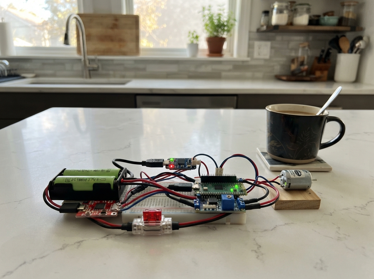
This project builds a protected dual-output power supply for robotics and maker applications, delivering regulated power to both a Motor 2040 controller and a Raspberry Pi Pico 2 W. The system combines a matched pair of 18650 lithium-ion cells with a dedicated BMS protection board, USB-C balance charger, inline fusing, and a buck converter to safely step down voltage for the Pico while maintaining full power delivery to the motor controller.
The guide provides a complete wiring diagram, parts list, and step-by-step assembly instructions to safely integrate the battery pack, protection circuitry, and charging system. All power management happens in hardware, allowing the Pico to focus on motor control logic without managing power distribution itself. Testing procedures ensure safe operation before connecting any external boards or motors.
Wiring diagram

Gather all the parts
Assemble it in 6 steps
1. Prepare the matched battery pair
Use two identical, unprotected 18650 lithium-ion cells of the same brand, capacity, and age. Charge them to the same voltage before putting them in the 2-cell holder. The holder creates one 7.4 V nominal battery pack: it reaches 8.4 V when full.
- Label the two cells as a pair and keep them together for this project.
- Do not mix old and new cells or different capacities; one cell can be overcharged or over-discharged even when the pack looks normal.
- Never use damaged, swollen, or bare loose cells; a short circuit can make lithium-ion cells very hot or start a fire.
2. Wire the battery protection board
With both cells removed from the holder, connect the holder BAT- lead to B- on bms_2s, the middle tap marked MID to B1, and BAT+ to B+. These three wires must go to the matching labels in that exact order.
- Use short, insulated wire sized for motor current, and check each label twice before soldering.
- The BMS is the safety board that disconnects the pack if a cell is drained too far, overcharged, or shorted.
- Do not reverse B+, B1, and B-; a wrong connection can permanently damage the protection board or battery cells.
- Do not insert the cells until all three BMS battery wires have been checked with a meter.
3. Connect the USB-C charger
Connect usb_c_charger OUT+ to the BMS P+ terminal and charger OUT- to the BMS P- terminal. Plugging a USB-C power supply into the charger later charges the protected 2-cell pack through these two wires.
- Use a USB-C wall adapter rated 5 V and at least 3 A.
- The charger must specifically say it is for a 2S, 8.4 V lithium-ion pack and has cell balancing.
- Do not use a common single-cell USB charger such as a TP4056; it cannot safely charge two cells connected in series.
- Do not power the charger from a 9 V or 12 V adapter unless its printed input rating explicitly allows it; this design assumes normal 5 V USB-C input.
4. Make the Motor 2040 outlet
Connect BMS P+ to motor_fuse IN, then connect motor_fuse OUT to the Motor 2040 EXT PWR pad. Connect BMS P- directly to the Motor 2040 GND power-input pad. Fit a 7.5 A blade fuse in motor_fuse.
- Keep these motor-power wires short and use heavier wire than the small signal wires.
- The fuse protects the wiring if a motor lead is crushed or a motor stalls.
- Do not connect this battery output to the Motor 2040 USB power input; use only EXT PWR and GND for the 2-cell battery.
- Make sure the positive wire goes to EXT PWR and the negative wire goes to GND — swapped power can damage the Motor 2040.
5. Make the Pico 2 W outlet
Connect BMS P+ to pico_fuse IN. Connect pico_fuse OUT to pico_buck VIN+, and connect pico_buck VIN- to BMS P-. Before the Pico is attached, power the circuit and adjust pico_buck until a meter reads exactly 5.0 V between VOUT+ and VOUT-. Then connect VOUT+ to the Pico 2 W VSYS pin and VOUT- to a Pico 2 W GND pin.
- Fit a 2 A blade fuse in pico_fuse.
- The buck converter turns the changing 6.0–8.4 V battery voltage into the steady 5 V the Pico needs.
- Do not connect the buck output to the Pico 3V3 pin; 5 V on that pin can damage the board.
- Set and measure the converter output before connecting the Pico; an incorrectly adjusted converter can damage the Pico.
6. Test before inserting boards
Before attaching either board, insert the cells and use a meter. Measure roughly 6.0–8.4 V between the Motor 2040 outlet positive and ground, and exactly 5.0 V between the Pico outlet positive and ground. Then disconnect power, attach both boards, and reconnect power.
- Test first with motors unplugged, then attach one motor at a time after the boards power normally.
- If a fuse blows, a wire gets warm, or you smell hot plastic, disconnect the battery immediately and inspect for a short circuit.
- Never leave lithium-ion charging unattended or charge the pack inside a sealed enclosure.
Review all connections
1. Connections between "battery_pack" and "Raspberry Pi Pico"
2. Connections between "bms_2s" and "Raspberry Pi Pico"
3. Connections between "motor_fuse" and "Raspberry Pi Pico"
4. Connections between "pico_fuse" and "Raspberry Pi Pico"
5. Connections between "pico_buck" and "Raspberry Pi Pico"
6. Connections between "usb_c_charger" and "Raspberry Pi Pico"
7. Connections between "pico2w_load" and "Raspberry Pi Pico"
Deploy the firmware
#include <Arduino.h>
// Power-distribution project: the battery, BMS, charger, fuses, and buck converter
// operate in hardware. This sketch intentionally leaves all Motor 2040 outputs off.
void setup() {
}

void loop() {
  delay(1000);
}
Remix this project
Make it yours in one click
Open a full copy of this project in your own Schematik workspace — diagram, code, parts, and assembly steps included. Swap the sensor, add features, or redesign the whole thing with AI. The author's original stays untouched.