Community project
Smart Assistive Cane Feedback
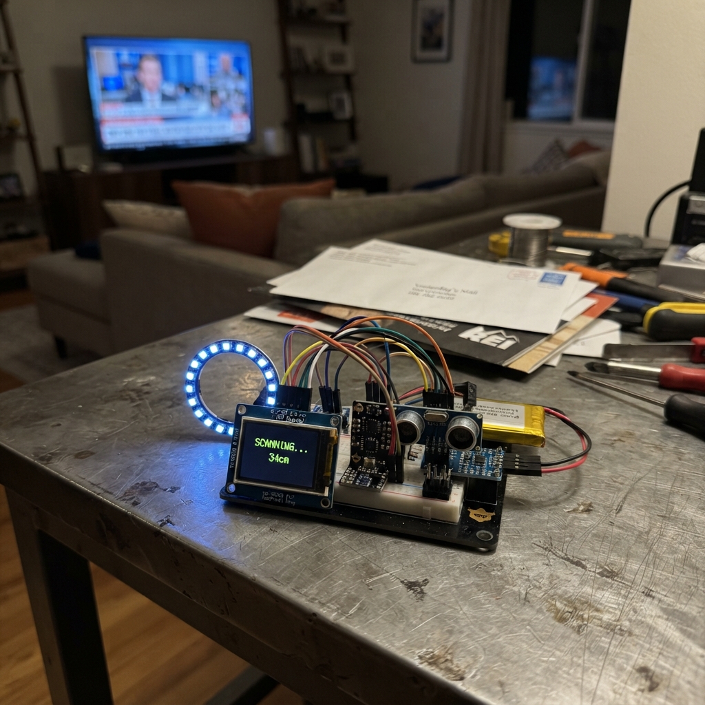
This smart assistive cane uses multiple distance sensors and motion detection to provide real-time obstacle feedback to the user through a combination of visual, haptic, and audio cues. The ESP32 coordinates input from three ultrasonic rangefinders, a time-of-flight sensor, a 6-axis motion sensor, and six user buttons to deliver alerts via a 2-inch TFT display, a 16-LED NeoPixel ring, vibration motors, and a laser pointer.
This guide provides a complete wiring diagram, parts list, and step-by-step assembly instructions for building the cane's electronics. The firmware handles sensor polling, multi-directional obstacle detection, fall detection via the MPU-6050, and user interface controls through the I2C button expander. Builders will learn how to integrate multiple sensor types, manage power distribution on a rechargeable lithium battery, and implement real-time feedback logic on an embedded system.
Wiring diagram

Gather all the parts
Assemble it in 6 steps
1. Make the battery power chain
With the battery unplugged, connect battery positive to the main power switch input, the switch output to the charger/boost module BAT input, and battery negative to the charger/boost ground. Connect the module 5 V output to the ESP32 VIN rail and its ground output to the shared ground rail.
- Use red wire for positive power and black wire for ground so you can trace the power path later.
- Do not connect or disconnect bare battery wires while the charger/boost module is powered; a short circuit can heat the battery and wiring quickly.
2. Wire the screen and shared sensors
Connect the ST7789 VCC to 3V3 and GND to GND. Connect SCK to GPIO18, MOSI to GPIO23, CS to GPIO5, DC to GPIO17, and RST to GPIO16; tie BL to 3V3 for a permanently lit screen. Connect the VL53L0X VIN to 5V, GND to GND, SDA to GPIO21, and SCL to GPIO22. Connect the MPU6050 VIN to 3V3, GND to GND, SDA to GPIO21, and SCL to GPIO22.
- The two I2C sensor wires share the same GPIO21 and GPIO22 connections; this is normal.
- Make sure VCC and GND are not swapped — swapped power can damage the screen or sensors.
3. Wire the three obstacle sensors safely
Connect all three HC-SR04 modules with VCC to 5V and GND to GND. Connect front TRIG to GPIO14, left TRIG to GPIO26, and right TRIG to GPIO27. Route each ECHO pin into its own 1 kΩ-to-2 kΩ divider: divider output goes to GPIO13 for front, GPIO34 for left, and GPIO35 for right; each divider ground goes to GND.
- Keep the three ultrasonic modules facing their intended directions and separate them slightly so their sound pulses do not interfere.
- Never wire a 5 V ECHO pin directly to the ESP32 — it can damage the 3.3 V input.
4. Add the light ring and six buttons
Connect the WS2812 ring VCC to 5V and GND to GND. Put the 330 Ω data resistor between GPIO4 and the ring DIN. Place the 1000 µF capacitor directly across the ring 5V and GND pins, with its marked negative stripe on GND. Connect the PCF8574 VCC to 3V3, GND to GND, SDA to GPIO21, and SCL to GPIO22. Wire one side of each pushbutton to GND and the other sides to PCF8574 P0 through P5.
- The PCF8574 lets all six buttons use the same two sensor wires instead of consuming six ESP32 pins.
- The capacitor stripe must go to ground; reversing an electrolytic capacitor can damage it.
5. Wire the motors, laser, and LEDs
Feed the AMS1117 regulator from 5V and GND, then use its 3V3 output for both vibration motors. Wire each motor negative lead to its matching AO3400A drain, each AO3400A source to GND, and the gates to GPIO33 for the front/rear pair and GPIO19 for the centre motor. Put one 1N5819 diode across each motor channel with the striped end on 3V3. Wire the laser and the LED cathodes through their AO3400A drains to GND; use GPIO32 for the laser driver gate and GPIO25 for the LED driver gate. Each LED needs its own series resistor from 5V to its positive leg.
- The long LED leg is positive and goes toward its resistor; the short leg goes toward the transistor-controlled negative side.
- Do not stare into the laser beam or aim it at people, animals, roads, or reflective surfaces.
6. Fit the reset switch and check every ground
Connect the reset pushbutton between ESP32 EN and GND. Before connecting the battery, check that every board and module has a ground wire back to the same GND rail, then inspect for loose strands or reversed battery wiring.
- Use a multimeter to confirm there is no short between 5V and GND before inserting the battery.
- A misplaced battery wire can damage the ESP32, charger, or battery.
Review all connections
1. Connections between "battery" and "ESP32"
2. Connections between "main_power_switch" and "ESP32"
3. Connections between "powerboost" and "ESP32"
4. Connections between "display" and "ESP32"
5. Connections between "tof" and "ESP32"
6. Connections between "imu" and "ESP32"
7. Connections between "buttons" and "ESP32"
8. Connections between "button_1" and "ESP32"
9. Connections between "button_2" and "ESP32"
10. Connections between "button_3" and "ESP32"
11. Connections between "button_4" and "ESP32"
12. Connections between "button_5" and "ESP32"
13. Connections between "button_6" and "ESP32"
14. Connections between "sonar_front" and "ESP32"
15. Connections between "sonar_left" and "ESP32"
16. Connections between "sonar_right" and "ESP32"
17. Connections between "echo_div_front" and "ESP32"
18. Connections between "echo_div_left" and "ESP32"
19. Connections between "echo_div_right" and "ESP32"
20. Connections between "ring" and "ESP32"
21. Connections between "ring_data_resistor" and "ESP32"
22. Connections between "ring_bulk_capacitor" and "ESP32"
23. Connections between "motor_regulator" and "ESP32"
24. Connections between "motor_a" and "ESP32"
25. Connections between "motor_b" and "ESP32"
26. Connections between "motor_driver_a" and "ESP32"
27. Connections between "motor_driver_b" and "ESP32"
28. Connections between "motor_flyback_diode" and "ESP32"
29. Connections between "laser" and "ESP32"
30. Connections between "laser_driver" and "ESP32"
31. Connections between "light_driver" and "ESP32"
32. Connections between "led_resistor_1" and "ESP32"
33. Connections between "led_resistor_2" and "ESP32"
34. Connections between "led_resistor_3" and "ESP32"
35. Connections between "uv_led_resistor" and "ESP32"
36. Connections between "white_led" and "ESP32"
37. Connections between "uv_led" and "ESP32"
38. Connections between "reset_switch" and "ESP32"
39. Connections between "motor_flyback_diode_b" and "ESP32"
Deploy the firmware
#include <Arduino.h>
#include <Wire.h>
#include <SPI.h>
#include <WiFi.h>
#include <WiFiUdp.h>
#include <Adafruit_GFX.h>
#include <Adafruit_ST7789.h>
#include <Adafruit_VL53L0X.h>
#include <Adafruit_NeoPixel.h>
#include <Adafruit_PCF8574.h>
#include <MPU6050.h>


// Forward declarations
uint16_t readSonarCm(uint8_t trig, uint8_t echo);
uint32_t colourForDistance(uint16_t cm);
void updateFeedback();
void drawScreenIfChanged();
void pollButtons();
void pollHat();

constexpr uint8_t TFT_SCK = 18;
constexpr uint8_t TFT_MOSI = 23;
constexpr uint8_t TFT_CS = 5;
constexpr uint8_t TFT_DC = 17;
constexpr uint8_t TFT_RST = 16;
constexpr uint8_t I2C_SDA = 21;
constexpr uint8_t I2C_SCL = 22;
constexpr uint8_t RING_PIN = 4;
constexpr uint8_t FRONT_TRIG = 14;
constexpr uint8_t FRONT_ECHO = 13;
constexpr uint8_t LEFT_TRIG = 26;
constexpr uint8_t LEFT_ECHO = 34;
constexpr uint8_t RIGHT_TRIG = 27;
constexpr uint8_t RIGHT_ECHO = 35;
constexpr uint8_t LASER_GATE = 32;
constexpr uint8_t LIGHT_GATE = 25;
constexpr uint8_t MOTOR_A_GATE = 33;
constexpr uint8_t MOTOR_B_GATE = 19;
constexpr uint16_t UDP_PORT = 4210;
constexpr uint16_t NEOPIXELS = 16;

Adafruit_ST7789 tft(TFT_CS, TFT_DC, TFT_RST);
Adafruit_VL53L0X tof;
Adafruit_NeoPixel ring(NEOPIXELS, RING_PIN, NEO_GRB + NEO_KHZ800);
Adafruit_PCF8574 buttons;
MPU6050 mpu;
WiFiUDP udp;

uint16_t frontCm = 999, leftCm = 999, rightCm = 999, tofMm = 9999;
uint8_t sonarIndex = 0;
bool laserOn = false;
bool lightsOn = false;
bool fallAlert = false;
String hatMessage = "Hat offline";
String previousScreen = "";
uint8_t lastButtons = 0x3F;
unsigned long lastSonarMs = 0;
unsigned long lastTofMs = 0;
unsigned long lastImuMs = 0;
unsigned long lastScreenMs = 0;

uint16_t readSonarCm(uint8_t trig, uint8_t echo) {
  digitalWrite(trig, LOW);
  delayMicroseconds(3);
  digitalWrite(trig, HIGH);
  delayMicroseconds(10);
  digitalWrite(trig, LOW);
  unsigned long duration = pulseIn(echo, HIGH, 25000UL);
  if (duration == 0) return 999;
  return static_cast<uint16_t>(duration / 58UL);
}

uint32_t colourForDistance(uint16_t cm) {
  if (cm < 35) return ring.Color(255, 0, 0);
  if (cm < 80) return ring.Color(255, 75, 0);
  if (cm < 150) return ring.Color(210, 170, 0);
  return ring.Color(0, 90, 0);
}

void updateFeedback() {
  uint16_t nearest = min(frontCm, min(leftCm, rightCm));
  uint32_t colour = fallAlert ? ring.Color(180, 0, 180) : colourForDistance(nearest);
  for (uint8_t i = 0; i < NEOPIXELS; ++i) ring.setPixelColor(i, colour);
  ring.show();

  bool danger = nearest < 80 || tofMm < 800 || fallAlert;
  bool leftDanger = leftCm < 80;
  bool rightDanger = rightCm < 80;
  digitalWrite(MOTOR_A_GATE, (danger || leftDanger) ? HIGH : LOW);
  digitalWrite(MOTOR_B_GATE, rightDanger ? HIGH : LOW);
}

void drawScreenIfChanged() {
  if (millis() - lastScreenMs < 150) return;
  lastScreenMs = millis();
  String state = String(frontCm) + "," + leftCm + "," + rightCm + "," + tofMm + "," + hatMessage + "," + fallAlert + "," + laserOn + "," + lightsOn;
  if (state == previousScreen) return;
  previousScreen = state;

  tft.fillScreen(ST77XX_BLACK);
  tft.setTextWrap(false);
  tft.setTextSize(2);
  tft.setTextColor(ST77XX_CYAN);
  tft.setCursor(8, 8);
  tft.print("SMART CANE");
  tft.setTextSize(2);
  tft.setTextColor(ST77XX_WHITE);
  tft.setCursor(8, 48); tft.printf("Front: %ucm", frontCm);
  tft.setCursor(8, 76); tft.printf("Left : %ucm", leftCm);
  tft.setCursor(8, 104); tft.printf("Right: %ucm", rightCm);
  tft.setCursor(8, 132); tft.printf("ToF  : %umm", tofMm);
  tft.setTextColor(fallAlert ? ST77XX_MAGENTA : ST77XX_GREEN);
  tft.setCursor(8, 166); tft.print(fallAlert ? "FALL ALERT" : "LOCAL SENSING OK");
  tft.setTextColor(ST77XX_YELLOW);
  tft.setCursor(8, 196); tft.print(hatMessage.substring(0, 24));
  tft.setTextSize(1);
  tft.setCursor(8, 222);
  tft.printf("Laser:%s Light:%s", laserOn ? "ON" : "OFF", lightsOn ? "ON" : "OFF");
}

void pollButtons() {
  uint8_t now = 0;
  for (uint8_t i = 0; i < 6; ++i) if (buttons.digitalRead(i)) now |= (1U << i);
  uint8_t pressed = lastButtons & ~now;
  if (pressed & (1U << 0)) laserOn = !laserOn;
  if (pressed & (1U << 1)) lightsOn = !lightsOn;
  if (pressed & (1U << 2)) fallAlert = false;
  if (pressed & (1U << 3)) hatMessage = "Help requested";
  digitalWrite(LASER_GATE, laserOn ? HIGH : LOW);
  digitalWrite(LIGHT_GATE, lightsOn ? HIGH : LOW);
  lastButtons = now;
}

void pollHat() {
  int packetSize = udp.parsePacket();
  if (!packetSize) return;
  char packet[96];
  int n = udp.read(packet, sizeof(packet) - 1);
  if (n > 0) {
    packet[n] = '\0';
    hatMessage = String(packet);
  }
}

void setup() {
  pinMode(FRONT_TRIG, OUTPUT); pinMode(LEFT_TRIG, OUTPUT); pinMode(RIGHT_TRIG, OUTPUT);
  pinMode(FRONT_ECHO, INPUT); pinMode(LEFT_ECHO, INPUT); pinMode(RIGHT_ECHO, INPUT);
  pinMode(LASER_GATE, OUTPUT); pinMode(LIGHT_GATE, OUTPUT);
  pinMode(MOTOR_A_GATE, OUTPUT); pinMode(MOTOR_B_GATE, OUTPUT);
  digitalWrite(LASER_GATE, LOW); digitalWrite(LIGHT_GATE, LOW);
  digitalWrite(MOTOR_A_GATE, LOW); digitalWrite(MOTOR_B_GATE, LOW);

  Wire.begin(I2C_SDA, I2C_SCL);
  buttons.begin(0x20, &Wire);
  for (uint8_t i = 0; i < 6; ++i) buttons.pinMode(i, INPUT_PULLUP);
  mpu.initialize();
  tof.begin(0x29, false, &Wire);

  SPI.begin(TFT_SCK, -1, TFT_MOSI, TFT_CS);
  tft.init(240, 320);
  tft.setRotation(1);
  ring.begin(); ring.setBrightness(40); ring.clear(); ring.show();

  WiFi.mode(WIFI_AP);
  WiFi.softAP("SmartCane", "caneassist");
  udp.begin(UDP_PORT);
  drawScreenIfChanged();
}

void loop() {
  unsigned long now = millis();
  if (now - lastSonarMs >= 90) {
    lastSonarMs = now;
    if (sonarIndex == 0) frontCm = readSonarCm(FRONT_TRIG, FRONT_ECHO);
    else if (sonarIndex == 1) leftCm = readSonarCm(LEFT_TRIG, LEFT_ECHO);
    else rightCm = readSonarCm(RIGHT_TRIG, RIGHT_ECHO);
    sonarIndex = (sonarIndex + 1) % 3;
    updateFeedback();
  }
  if (now - lastTofMs >= 150) {
    lastTofMs = now;
    VL53L0X_RangingMeasurementData_t measure;
    tof.rangingTest(&measure, false);
    if (measure.RangeStatus != 4) tofMm = measure.RangeMilliMeter;
  }
  if (now - lastImuMs >= 250) {
    lastImuMs = now;
    int16_t ax, ay, az, gx, gy, gz;
    mpu.getMotion6(&ax, &ay, &az, &gx, &gy, &gz);
    long magnitude = abs(ax) + abs(ay) + abs(az);
    if (magnitude > 52000L) fallAlert = true;
  }
  pollButtons();
  pollHat();
  drawScreenIfChanged();
}
Remix this project
Make it yours in one click
Open a full copy of this project in your own Schematik workspace — diagram, code, parts, and assembly steps included. Swap the sensor, add features, or redesign the whole thing with AI. The author's original stays untouched.
Related projects

Create A Complete Electrical Schematic Esp32 Sma
ESP32 · September 17, 2026Ayansh Agrawal
ESP32 Kare Ekran Projeleri
ESP32 · September 16, 2026Seref Ai
Component Qty --------------------------- ------
ESP32 · September 16, 2026Yathartha Chakrawal