Community project
Smart Badminton Racket Tracker
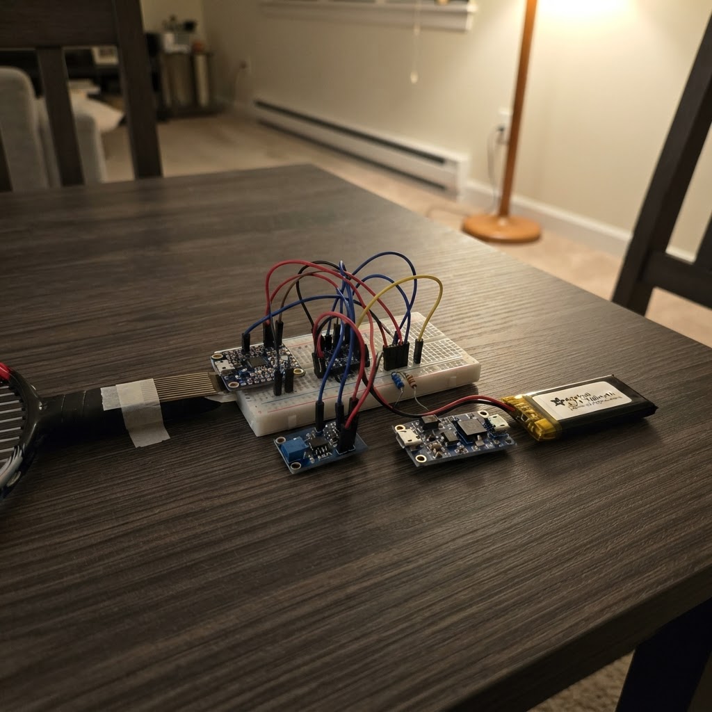
The Smart Badminton Racket Tracker is an instrumented racket handle that captures swing dynamics, impact forces, and grip pressure during play. Built around an ESP32 microcontroller, it combines a 9-DoF IMU for motion tracking, a force-sensitive resistor for grip analysis, and a vibration sensor to detect ball contact. The guide provides a complete parts list, wiring diagram, step-by-step assembly instructions for integrating sensors into the racket handle, and firmware with Bluetooth Low Energy connectivity to stream real-time sensor data to a mobile device or computer.
This project enables players and coaches to analyze swing mechanics, measure impact intensity, and track grip consistency. The battery-powered design with integrated charging circuitry allows extended play sessions, while the modular sensor layout makes it straightforward to customize the installation to different racket types and handle sizes.
Wiring diagram

Gather all the parts
Assemble it in 6 steps
1. Siapkan dan periksa komponen
Siapkan ESP32 DevKit v1, imu_9dof, grip_fsr, fsr_divider_resistor, impact_sensor, battery_lipo, charger_tp4056, dan regulator_3v3. Gunakan kabel fleksibel berisolasi, heat-shrink, dan wadah non-konduktif tipis. Lepaskan baterai dari rangkaian selama seluruh penyolderan.
- Untuk raket final, pindahkan rangkaian dari DevKit ke PCB kustom kecil berbasis ESP32-WROOM agar cukup masuk gagang.
- Tempatkan IMU sedekat mungkin ke sumbu memanjang gagang dan catat orientasi sumbu X/Y/Z-nya untuk kalibrasi perangkat lunak.
- Jangan menekan, melubangi, atau memanaskan battery_lipo.
- Pastikan tidak ada kawat atau PCB yang dapat bergerak/bergetar di dalam gagang.
2. Rakit catu daya LiPo yang terlindungi
Hubungkan battery_lipo positif ke charger_tp4056 B+ dan negatif ke charger_tp4056 B-. Hubungkan charger_tp4056 OUT+ ke regulator_3v3 VIN+ serta OUT- ke regulator_3v3 VIN-. Hubungkan regulator_3v3 VOUT+ ke rel 3.3 V dan VOUT- ke rel GND. Rel 3.3 V ini menuju pin 3.3V ESP32; rel GND menuju pin GND ESP32. Port USB-C charger_tp4056 hanya untuk pengisian 5 V.
- Atur atau beli TP4056 dengan arus pengisian yang sesuai baterai 500 mAh, sekitar 250–500 mA sesuai spesifikasi sel.
- Sebelum memasang ESP32, ukur keluaran regulator_3v3: harus 3.3 V terhadap GND.
- Jangan hubungkan OUT+ LiPo langsung ke pin 3.3V ESP32; tegangan sel penuh 4.2 V dapat merusak perangkat 3.3 V.
- Jangan menyalakan perangkat dari USB ESP32 dan keluaran regulator pada saat yang sama kecuali jalur daya sudah dirancang dengan power-path/isolasi.
- Isolasi semua sambungan baterai dengan heat-shrink untuk mencegah hubung singkat.
3. Pasang IMU 9-DoF
Hubungkan imu_9dof VIN ke rel 3.3 V, GND ke GND, SDA ke GPIO21 ESP32, SCL ke GPIO22 ESP32, dan INT ke GPIO27 ESP32. Biarkan CS serta SDO/ADR tidak terhubung untuk mode I2C alamat default 0x69.
- Buat kabel I2C sesingkat mungkin dan puntir ringan SDA-GND serta SCL-GND bila memungkinkan.
- Pasang IMU secara kaku pada dudukan kecil di pangkal gagang; jangan pada bagian grip yang lentur.
- Pastikan breakout imu_9dof benar-benar mendukung VIN 3.3 V. Jangan memberi 5 V ke pin GPIO ESP32.
- Jangan memakai GPIO0, GPIO2, GPIO12, atau GPIO15 untuk sensor karena berpengaruh pada proses boot ESP32.
4. Pasang sensor tekanan grip
Letakkan grip_fsr di bawah overgrip, pada lokasi genggaman telapak yang konsisten. Hubungkan Pin 1 grip_fsr ke 3.3 V. Hubungkan Pin 2 grip_fsr ke GPIO34 ESP32 dan ke End A fsr_divider_resistor. Hubungkan End B fsr_divider_resistor ke GND. Ini membentuk pembagi tegangan FSR dengan resistor pull-down 10 kΩ.
- Pakai lem tipis/flexible tape agar sensor tidak terlipat tajam; keluarkan kabel FSR sepanjang gagang sebelum menutup overgrip.
- GPIO34 hanya input dan sangat tepat untuk pembacaan ADC FSR.
- FSR bukan load-cell terkalibrasi; gunakan nilainya sebagai indeks/kelas kekuatan genggaman, kecuali dikalibrasi terhadap beban referensi.
- Jangan memberi 5 V ke pembagi tegangan FSR karena ADC ESP32 maksimum 3.3 V.
5. Pasang sensor impact
Pasang impact_sensor secara kaku di bagian pangkal gagang, bukan pada senar atau frame. Hubungkan VCC ke 3.3 V, GND ke GND, dan DO ke GPIO26 ESP32. Atur trimpot modul setelah perangkat hidup sehingga benturan ringan/gerakan normal tidak memicu, sedangkan pukulan nyata memicu secara konsisten.
- Gunakan impact_sensor sebagai petunjuk tambahan; keputusan impact utama sebaiknya divalidasi dari puncak percepatan IMU.
- Catat setelan ambang dan lakukan uji 20–30 pukulan untuk tiap pemain.
- SW-420 bersifat pemicu kasar dan dapat false-trigger akibat getaran pegangan; jangan menganggapnya sebagai satu-satunya bukti impact.
- Pastikan keluaran DO tidak lebih dari 3.3 V; beri daya modul dari 3.3 V, bukan 5 V.
6. Tata letak mekanik dalam gagang
Susun battery_lipo memanjang di bagian paling bawah gagang untuk menekan perubahan titik keseimbangan. Letakkan regulator_3v3 dan charger_tp4056 di dekat butt-cap agar port pengisian dapat diakses. Letakkan ESP32 dan imu_9dof di atas baterai pada sumbu tengah, dengan foam tipis non-konduktif untuk menahan komponen. Tempelkan impact_sensor pada struktur kaku pangkal gagang, sedangkan grip_fsr berada langsung di bawah overgrip.
- Targetkan total massa elektronik serendah mungkin; timbang raket sebelum/sesudah dan dokumentasikan perubahan balance point untuk penelitian.
- Gunakan strain relief pada semua kabel dan bungkus modul dengan Kapton/heat-shrink sebelum ditutup.
- Jangan menutup permanen sebelum uji tegangan, polaritas, I2C, BLE, dan sensor.
- Jaga port charger dari keringat/kelembapan dan jangan mengisi baterai saat raket sedang dipakai.
Review all connections
1. Connections between "imu_9dof" and "ESP32"
2. Connections between "grip_fsr" and "ESP32"
3. Connections between "impact_sensor" and "ESP32"
4. Connections between "battery_lipo" and "ESP32"
5. Connections between "charger_tp4056" and "ESP32"
6. Connections between "regulator_3v3" and "ESP32"
7. Connections between "fsr_divider_resistor" and "ESP32"
Deploy the firmware
#include <Arduino.h>
#include <Wire.h>
#include <ArduinoJson.h>
#include <Adafruit_ICM20948.h>
#include <Adafruit_Sensor.h>
#include <BLEDevice.h>
#include <BLEServer.h>
#include <BLEUtils.h>
#include <BLE2902.h>


// Forward declarations
void IRAM_ATTR onVibration();
float magnitude3(float x, float y, float z);
void setupBle();

constexpr int SDA_PIN = 21;
constexpr int SCL_PIN = 22;
constexpr int IMU_INT_PIN = 27;
constexpr int IMPACT_PIN = 26;
constexpr int GRIP_PIN = 34;
constexpr uint16_t SAMPLE_HZ = 100;
constexpr uint32_t SAMPLE_PERIOD_US = 1000000UL / SAMPLE_HZ;
constexpr float IMPACT_ACCEL_THRESHOLD_G = 5.0f;
constexpr float RAD_TO_DEG = 57.2957795f;

const char *DEVICE_NAME = "SmartRacket-001";
const char *SERVICE_UUID = "7d315ef1-8e28-4c6c-a46b-e719b8e21a01";
const char *STREAM_UUID = "7d315ef2-8e28-4c6c-a46b-e719b8e21a01";

Adafruit_ICM20948 icm;
BLECharacteristic *streamCharacteristic = nullptr;
volatile bool vibrationEdge = false;
bool clientConnected = false;
uint32_t lastSampleUs = 0;
uint32_t sequenceNumber = 0;
uint32_t swingCount = 0;
bool inSwing = false;

void IRAM_ATTR onVibration() {
  vibrationEdge = true;
}

class ServerCallbacks : public BLEServerCallbacks {
  void onConnect(BLEServer *server) override {
    clientConnected = true;
  }

  void onDisconnect(BLEServer *server) override {
    clientConnected = false;
    BLEDevice::startAdvertising();
  }
};

float magnitude3(float x, float y, float z) {
  return sqrtf(x * x + y * y + z * z);
}

void setupBle() {
  BLEDevice::init(DEVICE_NAME);
  BLEServer *server = BLEDevice::createServer();
  server->setCallbacks(new ServerCallbacks());
  BLEService *service = server->createService(SERVICE_UUID);
  streamCharacteristic = service->createCharacteristic(
      STREAM_UUID,
      BLECharacteristic::PROPERTY_NOTIFY | BLECharacteristic::PROPERTY_READ);
  streamCharacteristic->addDescriptor(new BLE2902());
  streamCharacteristic->setValue("{\"status\":\"ready\"}");
  service->start();
  BLEAdvertising *advertising = BLEDevice::getAdvertising();
  advertising->addServiceUUID(SERVICE_UUID);
  advertising->setScanResponse(true);
  BLEDevice::startAdvertising();
}

void setup() {
  Serial.begin(115200);
  pinMode(IMPACT_PIN, INPUT);
  pinMode(IMU_INT_PIN, INPUT);
  analogReadResolution(12);
  attachInterrupt(digitalPinToInterrupt(IMPACT_PIN), onVibration, RISING);

  Wire.begin(SDA_PIN, SCL_PIN);
  if (!icm.begin_I2C(0x69, &Wire)) {
    Serial.println("ICM-20948 tidak ditemukan pada alamat I2C 0x69.");
    while (true) {
      delay(1000);
    }
  }

  icm.setAccelRange(ICM20948_ACCEL_RANGE_16_G);
  icm.setGyroRange(ICM20948_GYRO_RANGE_2000_DPS);
  icm.setAccelRateDiv(10);
  icm.setGyroRateDiv(10);
  setupBle();
  lastSampleUs = micros();
}

void loop() {
  const uint32_t nowUs = micros();
  if (static_cast<uint32_t>(nowUs - lastSampleUs) < SAMPLE_PERIOD_US) {
    return;
  }
  lastSampleUs += SAMPLE_PERIOD_US;

  sensors_event_t accel;
  sensors_event_t gyro;
  sensors_event_t temperature;
  sensors_event_t mag;
  icm.getEvent(&accel, &gyro, &temperature, &mag);

  const float ax = accel.acceleration.x;
  const float ay = accel.acceleration.y;
  const float az = accel.acceleration.z;
  const float gxDps = gyro.gyro.x * RAD_TO_DEG;
  const float gyDps = gyro.gyro.y * RAD_TO_DEG;
  const float gzDps = gyro.gyro.z * RAD_TO_DEG;
  const float accelG = magnitude3(ax, ay, az) / 9.80665f;
  const float gyroDps = magnitude3(gxDps, gyDps, gzDps);
  const int gripRaw = analogRead(GRIP_PIN);

  // Orientation is a tilt/heading estimate for streaming. Gateway/server should
  // perform calibrated AHRS fusion for analysis and replay.
  const float rollDeg = atan2f(ay, az) * RAD_TO_DEG;
  const float pitchDeg = atan2f(-ax, sqrtf(ay * ay + az * az)) * RAD_TO_DEG;
  float headingDeg = atan2f(mag.magnetic.y, mag.magnetic.x) * RAD_TO_DEG;
  if (headingDeg < 0.0f) {
    headingDeg += 360.0f;
  }

  const bool impactByImu = accelG >= IMPACT_ACCEL_THRESHOLD_G;
  const bool impact = vibrationEdge || impactByImu;
  vibrationEdge = false;

  const bool swingingNow = gyroDps > 180.0f || accelG > 1.8f;
  if (swingingNow && !inSwing) {
    ++swingCount;
  }
  inSwing = swingingNow;

  StaticJsonDocument<512> packet;
  packet["schema"] = "smart-racket.v1";
  packet["player_id"] = "001";
  packet["device_id"] = DEVICE_NAME;
  packet["sequence"] = sequenceNumber++;
  packet["timestamp_ms"] = millis();
  packet["sample_hz"] = SAMPLE_HZ;
  JsonArray acceleration = packet.createNestedArray("acceleration_mps2");
  acceleration.add(ax);
  acceleration.add(ay);
  acceleration.add(az);
  JsonArray gyroscope = packet.createNestedArray("gyroscope_dps");
  gyroscope.add(gxDps);
  gyroscope.add(gyDps);
  gyroscope.add(gzDps);
  JsonArray magnetic = packet.createNestedArray("magnetic_ut");
  magnetic.add(mag.magnetic.x);
  magnetic.add(mag.magnetic.y);
  magnetic.add(mag.magnetic.z);
  JsonObject orientation = packet.createNestedObject("orientation_deg");
  orientation["roll"] = rollDeg;
  orientation["pitch"] = pitchDeg;
  orientation["heading"] = headingDeg;
  packet["acceleration_magnitude_g"] = accelG;
  packet["angular_speed_dps"] = gyroDps;
  packet["grip_raw_12bit"] = gripRaw;
  packet["impact"] = impact;
  packet["swing_active"] = swingingNow;
  packet["swing_count"] = swingCount;

  char json[512];
  const size_t length = serializeJson(packet, json, sizeof(json));
  Serial.write(reinterpret_cast<const uint8_t *>(json), length);
  Serial.println();
  if (clientConnected) {
    streamCharacteristic->setValue(reinterpret_cast<uint8_t *>(json), length);
    streamCharacteristic->notify();
  }
}
Remix this project
Make it yours in one click
Open a full copy of this project in your own Schematik workspace — diagram, code, parts, and assembly steps included. Swap the sensor, add features, or redesign the whole thing with AI. The author's original stays untouched.