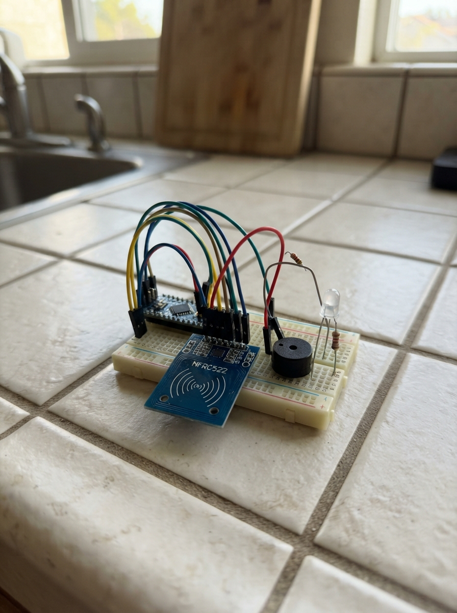
This RFID Badge Validation Station reads proximity cards and badges to authenticate them against a stored list of authorized IDs. Built around an Arduino Uno with an MFRC522 RFID reader, RGB LED, and piezo buzzer, the station provides visual and audio feedback for valid and invalid badge scans.
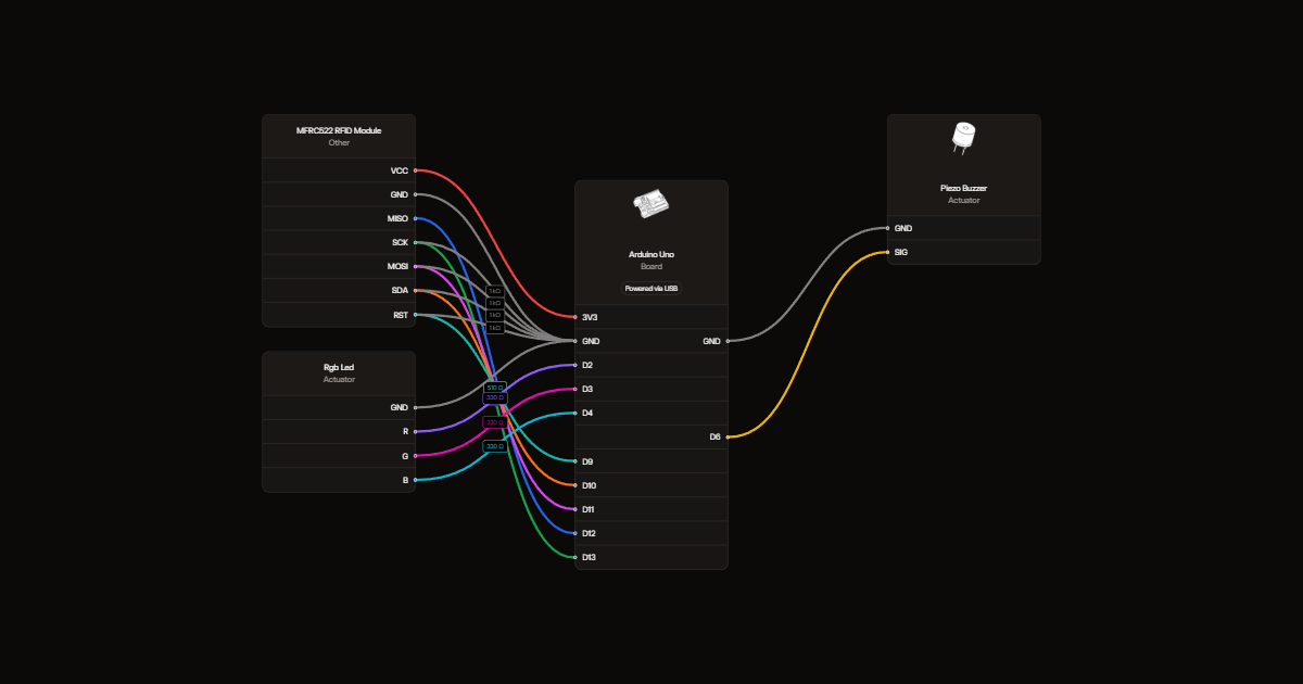
The guide includes a complete wiring diagram showing how to connect the RFID module via SPI, wire the RGB LED with current-limiting resistors, and integrate the buzzer for audio alerts. Assembly steps cover component preparation, power delivery to the reader, signal level conversion, and LED/buzzer integration. The provided firmware handles badge enrollment, EEPROM storage of up to 20 authorized IDs, and real-time validation with color-coded responses.
Wiring diagram
Gather all the parts
Assemble it in 5 steps
1. Préparer les composants
Débrancher l'USB. Prévoir le RC522, un petit piézo passif, une LED RGB à cathode commune, trois résistances de 330 Ω, quatre de 510 Ω et quatre de 1 kΩ. Le convertisseur à huit canaux est supprimé.
2. Alimenter le lecteur
Relier VCC du RC522 au 3.3 V de l'Uno et GND au GND.
- Ne jamais alimenter le RC522 en 5 V. La consommation totale sur la sortie 3.3 V doit rester sous 50 mA.
3. Abaisser les quatre signaux
Pour chaque signal, relier la broche Uno à une résistance de 510 Ω. Relier son autre extrémité à la broche RC522 et à une résistance de 1 kΩ allant au GND. Répéter pour D13 → SCK (horloge), D11 → MOSI (données envoyées), D10 → SDA (sélection) et D9 → RST (réinitialisation). Relier MISO directement à D12 (données reçues).
- Garder les fils courts. Laisser IRQ libre. SDA est ici la sélection SPI, pas une liaison I2C.
- Chaque paire de résistances produit environ 3.3 V à partir du signal 5 V. Ne pas inverser les deux valeurs.
4. Brancher la LED et le buzzer
Relier la cathode commune de la LED au GND. Relier D2 à la patte rouge à travers redRes de 330 Ω, D3 à la verte à travers greenRes de 330 Ω et D4 à la bleue à travers blueRes de 330 Ω. Relier SIG du piézo à D6 et son autre patte au GND.
- Vérifier le repérage des pattes de votre LED. Chaque couleur doit avoir sa propre résistance. Ce montage ne convient pas à une LED de puissance ni à un buzzer électromagnétique.
5. Déployer et tester
Vérifier le câblage, brancher l'USB et appuyer sur Deploy. Présenter un badge 13.56 MHz compatible RC522. Le premier badge est mémorisé comme autorisé même après extinction. Bleu signifie attente, vert et un bip signifie accepté, rouge et deux bips signifie refusé. Jusqu’à 20 badges sont conservés après extinction. Dans le moniteur série à 9600 bauds, envoyer A puis présenter un nouveau badge pour l’ajouter. Répéter A pour chaque ajout. C annule un ajout, L affiche le nombre de badges et X efface tous les badges. Après effacement, le premier badge présenté devient autorisé. Le badge anciennement enregistré est conservé lors de cette mise à jour.
- Les identifiants sont copiables. Ce prototype ne sécurise pas une porte et ne valide pas les cartes bancaires ou de transport.
Review all connections
1. Connections between "reader" and "Arduino"
2. Connections between "buzzer" and "Arduino"
3. Connections between "rgb" and "Arduino"
4. Connections between "redRes" and "Arduino"
5. Connections between "greenRes" and "Arduino"
6. Connections between "blueRes" and "Arduino"
7. Connections between "clockTop" and "Arduino"
8. Connections between "clockBottom" and "Arduino"
9. Connections between "dataTop" and "Arduino"
10. Connections between "dataBottom" and "Arduino"
11. Connections between "selectTop" and "Arduino"
12. Connections between "selectBottom" and "Arduino"
13. Connections between "resetTop" and "Arduino"
14. Connections between "resetBottom" and "Arduino"
Deploy the firmware
#include <Arduino.h>
#include <SPI.h>
#include <MFRC522.h>
#include <EEPROM.h>

constexpr byte RED=2, GREEN=3, BLUE=4, BUZZER=6;
MFRC522 reader(10,9);
constexpr byte MAX_BADGES=20, MAGIC=0xB8;
byte badgeCount=0;
bool enrollNext=false;
int slotAddress(byte slot){ return 2+11*slot; }
bool validSize(byte n){ return n==4 || n==7 || n==10; }
bool knownBadge(){
  for(byte slot=0;slot<badgeCount;slot++){
    int a=slotAddress(slot);
    if(EEPROM.read(a)!=reader.uid.size) continue;
    bool same=true;
    for(byte i=0;i<reader.uid.size;i++)
      if(EEPROM.read(a+1+i)!=reader.uid.uidByte[i]) same=false;
    if(same) return true;
  }
  return false;
}
bool ready=false;
unsigned long feedbackEnd=0;
void color(bool r,bool g,bool b){
  digitalWrite(RED,r); digitalWrite(GREEN,g); digitalWrite(BLUE,b);
}
void idle(){ color(false,false,true); }
void saveBadge(){
  int a=slotAddress(badgeCount);
  EEPROM.update(a,reader.uid.size);
  for(byte i=0;i<reader.uid.size;i++) EEPROM.update(a+1+i,reader.uid.uidByte[i]);
  EEPROM.update(1,++badgeCount);
}
void loadBadges(){
  if(EEPROM.read(0)==0xA7 && validSize(EEPROM.read(1))){
    byte n=EEPROM.read(1), old[10];
    for(byte i=0;i<n;i++) old[i]=EEPROM.read(2+i);
    EEPROM.update(0,0);
    EEPROM.update(2,n);
    for(byte i=0;i<n;i++) EEPROM.update(3+i,old[i]);
    EEPROM.update(1,1); EEPROM.update(0,MAGIC);
  }
  if(EEPROM.read(0)==MAGIC){
    badgeCount=EEPROM.read(1);
    if(badgeCount>MAX_BADGES) badgeCount=0;
    for(byte i=0;i<badgeCount;i++)
      if(!validSize(EEPROM.read(slotAddress(i)))) { badgeCount=0; break; }
  }
  if(!badgeCount){ EEPROM.update(1,0); EEPROM.update(0,MAGIC); }
}
void setup(){
  pinMode(RED,OUTPUT); pinMode(GREEN,OUTPUT); pinMode(BLUE,OUTPUT); pinMode(BUZZER,OUTPUT);
  Serial.begin(9600);
  loadBadges();
  SPI.begin(); reader.PCD_Init(); delay(10);
  byte version=reader.PCD_ReadRegister(MFRC522::VersionReg);
  ready=version!=0 && version!=0xFF;
  if(!ready){ color(true,false,false); Serial.println(F("Erreur RC522 : verifier alimentation et fils, puis redemarrer.")); return; }
  idle();
  Serial.println(F("Station prete. A : ajouter un badge, C : annuler, L : nombre, X : tout effacer."));
  if(!badgeCount) Serial.println(F("Presenter votre badge : il sera memorise comme autorise."));
}
void loop(){
  if(!ready) return;
  if(Serial.available()){
    char c=Serial.read();
    if(c=='X' || c=='x'){
      EEPROM.update(1,0); badgeCount=0; enrollNext=false;
      Serial.println(F("Memoire effacee. Le prochain badge sera autorise."));
    }else if(c=='A' || c=='a'){
      enrollNext=badgeCount<MAX_BADGES;
      Serial.println(enrollNext ? F("Presenter le badge a ajouter. C pour annuler.") : F("Memoire pleine : 20 badges."));
    }else if(c=='C' || c=='c'){
      enrollNext=false; Serial.println(F("Ajout annule."));
    }else if(c=='L' || c=='l'){
      Serial.print(F("Badges autorises : ")); Serial.println(badgeCount);
    }
  }
  if(feedbackEnd){
    if((long)(millis()-feedbackEnd)<0) return;
    feedbackEnd=0; idle();
  }
  if(!reader.PICC_IsNewCardPresent() || !reader.PICC_ReadCardSerial()) return;
  Serial.print(F("UID : "));
  for(byte i=0;i<reader.uid.size;i++){
    if(reader.uid.uidByte[i]<16) Serial.print('0');
    Serial.print(reader.uid.uidByte[i],HEX); Serial.print(' ');
  }
  Serial.println();
  bool enrolled=false;
  bool accepted=validSize(reader.uid.size) && knownBadge();
  if(validSize(reader.uid.size) && (!badgeCount || enrollNext)){
    if(!accepted && badgeCount<MAX_BADGES){ saveBadge(); enrolled=true; accepted=true; }
    enrollNext=false;
  }
  reader.PICC_HaltA(); reader.PCD_StopCrypto1();
  if(accepted){
    color(false,true,false); tone(BUZZER,4000,160);
    Serial.println(enrolled ? F("Badge memorise et accepte.") : F("ACCEPTE"));
  }else{
    color(true,false,false); tone(BUZZER,2200,120); delay(180); tone(BUZZER,2200,120);
    Serial.println(F("REFUSE"));
  }
  feedbackEnd=millis()+1000;
}
Remix this project
Make it yours in one click
Open a full copy of this project in your own Schematik workspace, diagram, code, parts, and assembly steps included. Swap the sensor, add features, or redesign the whole thing with AI. The author's original stays untouched.