Community project
Smart Classroom Welcome Monitor
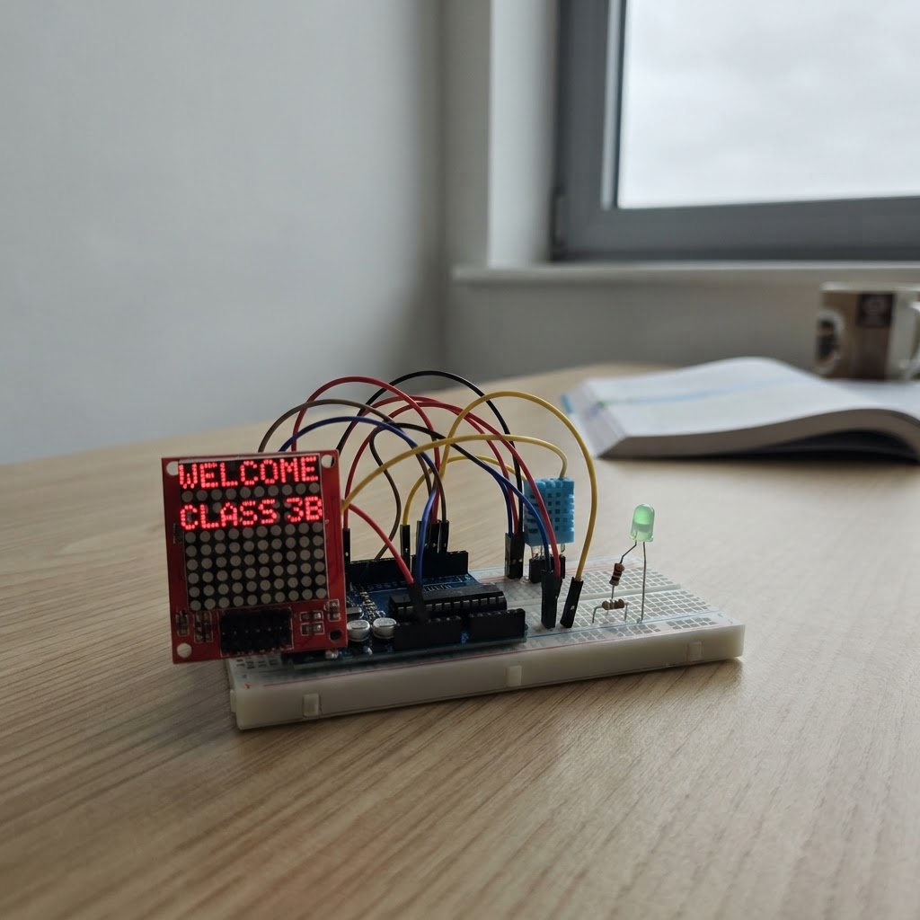
This smart classroom monitor displays real-time temperature and humidity readings on an LED matrix while alerting when the room gets too warm. Built around an Arduino Uno, DHT11 sensor, and MAX7219 LED matrix display, it continuously monitors classroom conditions and triggers a red LED warning light if temperature exceeds a configurable threshold.
The guide includes a complete wiring diagram showing breadboard layout, a full parts list with recommended suppliers, Arduino firmware with configurable thresholds and scroll speed, and step-by-step assembly instructions. Readers will learn how to wire SPI communication to the LED matrix, integrate analog sensor readings, and implement real-time environmental monitoring on a microcontroller.
Wiring diagram

Gather all the parts
Assemble it in 5 steps
1. Breadboard power rails
Connect the UNO's 5V pin to the breadboard's red (+) rail and GND to the blue (−) rail. This powers all components from the board's USB supply.
- Double-check the polarity — 5V to red, GND to blue.
2. Wire the MAX7219 LED Matrix
Plug the MAX7219 module into the breadboard. Connect: • VCC → 5V rail • GND → GND rail • DIN → UNO D11 • CLK → UNO D13 • CS → UNO D8
- DIN, CLK and CS are the only three signal wires needed.
- If you have more than one panel, daisy-chain DOUT of the first into DIN of the second and change MAX_DEVICES to 2 in the firmware.
3. Wire the DHT11 sensor
Plug the DHT11 module into the breadboard. Connect: • VCC (or +) → 5V rail • GND (or −) → GND rail • DATA (or S/OUT) → UNO D2
- The Elegoo kit DHT11 is a 3-pin module — the middle pin is DATA.
- Leave at least 1 cm clearance from heat sources for accurate readings.
4. Wire the red LED and resistor
Insert the 220 Ω resistor between UNO D3 and the LED's ANODE (longer leg). Connect the LED's CATHODE (shorter leg) to GND rail.
- The longer leg of the LED is the anode (+); the flat side of the LED body marks the cathode (−).
- Never connect an LED directly to a GPIO pin without the resistor — it will burn out.
5. Power up and verify
Plug the UNO into USB. The LED matrix should start scrolling temperature and humidity within 2 seconds of power-on. The red LED lights up automatically when the temperature exceeds 27 °C.
- Open Serial Monitor at 9600 baud to see live sensor readings.
- If the matrix is too dim or too bright, change the setIntensity(4) value (0–15) in the firmware and redeploy.
Review all connections
1. Connections between "dht11" and "Arduino"
2. Connections between "r1" and "Arduino"
3. Connections between "red_led" and "Arduino"
4. Connections between "matrix" and "Arduino"
Deploy the firmware
#include <Arduino.h>
#include <DHT.h>
#include <MD_Parola.h>
#include <MD_MAX72xx.h>
#include <SPI.h>

// ── Pin definitions ───────────────────────────────────────────────
#define DHT_PIN         2
#define LED_PIN         3
#define MATRIX_DIN_PIN  11
#define MATRIX_CLK_PIN  13
#define MATRIX_CS_PIN   8

// ── Config ────────────────────────────────────────────────────────
#define DHTTYPE         DHT11
#define MAX_DEVICES     1          // Change to 2, 3 … for more panels
#define SCROLL_SPEED    120        // Lower = faster scroll (ms per step)
#define HOT_THRESHOLD   27.0f      // °C — red LED turns on above this
#define SENSOR_INTERVAL 3000UL     // ms between sensor reads

// ── Objects ───────────────────────────────────────────────────────

// Forward declarations
void readSensor();

DHT dht(DHT_PIN, DHTTYPE);
MD_Parola matrix = MD_Parola(MD_MAX72XX::FC16_HW, MATRIX_CS_PIN, MAX_DEVICES);

// ── State ─────────────────────────────────────────────────────────
char displayBuf[32];
float lastTemp = 0.0f;
float lastHum  = 0.0f;
unsigned long lastSensorRead = 0;

// ── Helpers ───────────────────────────────────────────────────────
void readSensor() {
    float t = dht.readTemperature();
    float h = dht.readHumidity();
    if (!isnan(t)) lastTemp = t;
    if (!isnan(h)) lastHum  = h;

    // Red LED
    digitalWrite(LED_PIN, lastTemp > HOT_THRESHOLD ? HIGH : LOW);

    // Build display string  e.g.  "Temp:24C  Hum:55%"
    snprintf(displayBuf, sizeof(displayBuf),
             "Temp:%dC  Hum:%d%%",
             (int)round(lastTemp), (int)round(lastHum));
}

void setup() {
    Serial.begin(9600);
    pinMode(LED_PIN, OUTPUT);
    digitalWrite(LED_PIN, LOW);

    dht.begin();

    matrix.begin();
    matrix.setIntensity(4);          // 0 (dim) – 15 (bright)
    matrix.setTextAlignment(PA_LEFT);

    // First sensor read
    delay(2000);                     // DHT11 warm-up
    readSensor();

    // Kick off first scroll
    matrix.displayScroll(displayBuf, PA_LEFT, PA_SCROLL_LEFT, SCROLL_SPEED);

    Serial.println(F("Smart Classroom ready."));
}

void loop() {
    // Update display on each scroll completion
    if (matrix.displayAnimate()) {

        // Time to refresh sensor?
        unsigned long now = millis();
        if (now - lastSensorRead >= SENSOR_INTERVAL) {
            lastSensorRead = now;
            readSensor();
            Serial.print(F("Temp: ")); Serial.print(lastTemp);
            Serial.print(F(" C  Hum: ")); Serial.print(lastHum);
            Serial.println(F(" %"));
        }

        // Restart the scroll with the (possibly updated) buffer
        matrix.displayScroll(displayBuf, PA_LEFT, PA_SCROLL_LEFT, SCROLL_SPEED);
    }
}
Remix this project
Make it yours in one click
Open a full copy of this project in your own Schematik workspace — diagram, code, parts, and assembly steps included. Swap the sensor, add features, or redesign the whole thing with AI. The author's original stays untouched.