Community project
Smart Glasses In Built Local Ai Model Cloud
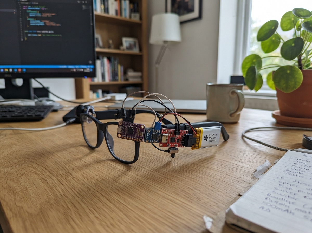
Build wearable smart glasses powered by an ESP32 that combine local voice recognition, audio feedback, and camera capture in a compact 3D-printed frame. The SU-03T voice recognition module processes commands locally, while the bone conductor transducer delivers audio directly to the wearer's skull without blocking ambient sound. A web interface streams camera feeds and processes voice commands, making this an ideal platform for hands-free AR applications, accessibility tools, or IoT device control.
This guide provides a complete parts list, wiring diagrams for the audio amplifier circuit, voice control module, and battery charging system, plus step-by-step assembly instructions for the 3D-printed frame and electronics pods. The included Arduino firmware handles camera initialization, I2S audio output, voice module communication, and a local web server—everything needed to get the glasses running and responding to voice commands right out of the box.
Wiring diagram

Gather all the parts
Assemble it in 6 steps
1. Print and prepare the glasses frame
Print the frame front, right-temple electronics pod, left-temple audio pod, and rear battery cover from the XIAO smart-glasses frame design in PETG or tough PLA. Remove loose plastic from the camera opening and cable channels, then check that the XIAO camera lens can look forward without the frame blocking it.
- Use a dark, non-shiny filament around the camera opening so reflections do not appear in photos.
- Make the electronics pods removable with small screws or a snug slide cover; you will need access for charging and debugging.
- Do not wear the prototype until every sharp edge, screw end, and soldered joint is covered; exposed metal can scratch skin or short the battery.
2. Mount the controller and camera
Place the Seeed Studio XIAO ESP32-S3 Sense in the bridge or right-front pocket with its camera lens centered in the front opening and its USB-C connector still reachable. Secure it with a thin foam pad and a small nylon strap or a tiny amount of removable adhesive; do not cover the microphone opening or camera lens.
- Route wires into the right temple before fixing the board permanently.
- Keep the board clear of metal spectacle hinges because they can touch pads underneath it.
- Do not put glue over the camera lens, microphone opening, USB-C connector, or antenna end of the XIAO; the camera, sound pickup, charging, and wireless link can stop working.
3. Wire the audio pod
In the left temple pod, connect the MAX98357A amplifier to the XIAO: BCLK → GPIO1 (audio timing), LRC → GPIO2 (audio timing), DIN → GPIO3 (audio sound data), VIN → 3V3 (power), and GND → GND (ground). Connect amplifier SPK+ → bone transducer SPEAKER+ (audio output) and SPK- → bone transducer SPEAKER- (audio output). Tape the transducer flat against the temple-contact pad so it can vibrate the bone just in front of your ear.
- Twist the two wires from SPK+ and SPK- together along the temple; this reduces noise and keeps the wiring neat.
- The bone transducer does not connect to ground; both of its wires go only to the amplifier speaker terminals.
- Do not connect either bone-transducer wire to GND or a XIAO pin — the amplifier’s two speaker outputs must stay isolated or the amplifier can be damaged.
4. Wire voice control and the button
Mount the SU-03T module in the right temple with its microphone hole facing outward. Connect VCC → 3V3 (power), GND → GND (ground), DATA → GPIO5 (local voice-event signal), TX → GPIO44/D7 (voice-module message to the XIAO), and RX → GPIO43/D6 (message from the XIAO). Connect one push-button leg → GPIO4 (signal) and the other push-button leg → GND (ground); place the button where your index finger can reach it on the right temple.
- Keep the SU-03T microphone away from the bone transducer so playback vibration does not trigger voice commands.
- Use thin flexible silicone-insulated wire through the hinge area and leave a small service loop so opening the arms does not pull on solder joints.
- All of these control wires are 3.3 V signals. Do not feed 5 V into GPIO4, GPIO5, GPIO43, or GPIO44 because that can permanently damage the XIAO.
5. Build the protected battery pod
In the rear/right temple pod, connect LiPo + → TP4056 B+ (battery positive) and LiPo - → TP4056 B- (battery negative). Connect TP4056 OUT+ → slide-switch COM (protected power), slide-switch A → regulator VIN (switched power), TP4056 OUT- → regulator GND (ground), and regulator VOUT → 3V3 (regulated power for the XIAO, voice module, and amplifier). Keep the TP4056 USB input reachable through a printed opening: IN+ → USB charging cable +5 V (charging power) and IN- → USB charging cable ground (charging ground).
- Put the battery at the back of the temple or behind the ear to counterbalance the controller near the front.
- Use heat-shrink tubing over every battery connection and strain-relief the battery lead before closing the pod.
- Never connect the LiPo directly to the XIAO or to the 3V3 rail; a fully charged cell can be above the safe 3.3 V supply voltage.
- Charge the battery only while it is inside a non-flammable area and stop immediately if the cell swells, becomes hot, or has damaged insulation.
6. Close the frame and do a safe first power check
Before wearing the frame, inspect that no bare wire crosses another bare wire, close the pods, move the slide switch to off, then plug USB into the TP4056 charging input until the charger indicates the battery is charged. Turn the switch on; the XIAO should start and the bone transducer should play a short two-note ready sound.
- Use the USB-C port on the XIAO for firmware deployment; use the TP4056 USB input only for battery charging.
- The phone/desktop control page is broadcast by the glasses as Wi-Fi network “Glasses-Control”; its password is “glasses2026” and the control address is printed over USB serial after startup.
- Keep the first audio test quiet and hold the transducer away from your head; high vibration against the temple can be uncomfortable.
Review all connections
1. Connections between "audio_amp" and "ESP32"
2. Connections between "ptt_button" and "ESP32"
3. Connections between "voice_module" and "ESP32"
4. Connections between "lipo_battery" and "ESP32"
5. Connections between "lipo_charger" and "ESP32"
6. Connections between "power_switch" and "ESP32"
7. Connections between "power_regulator" and "ESP32"
Deploy the firmware
#include <Arduino.h>
#include <WiFi.h>
#include <WebServer.h>
#include <esp_camera.h>
#include <driver/i2s.h>

// External wiring on the XIAO ESP32-S3 Sense.

// Forward declarations
void playTone(uint16_t hz, uint16_t durationMs);
void signalCommand();
void handleCommand(const String &command);
void setupAudio();
void setupCamera();
void serveCapture();
void setupWeb();

constexpr int I2S_BCLK_PIN = 1;
constexpr int I2S_LRCLK_PIN = 2;
constexpr int I2S_DOUT_PIN = 3;
constexpr int PTT_BUTTON_PIN = 4;
constexpr int VOICE_DATA_PIN = 5;
constexpr int VOICE_RX_PIN = 44;
constexpr int VOICE_TX_PIN = 43;

// XIAO ESP32-S3 Sense OV2640 camera wiring.
constexpr int CAM_PWDN = -1;
constexpr int CAM_RESET = -1;
constexpr int CAM_XCLK = 10;
constexpr int CAM_SIOD = 40;
constexpr int CAM_SIOC = 39;
constexpr int CAM_D7 = 48;
constexpr int CAM_D6 = 11;
constexpr int CAM_D5 = 12;
constexpr int CAM_D4 = 14;
constexpr int CAM_D3 = 16;
constexpr int CAM_D2 = 18;
constexpr int CAM_D1 = 17;
constexpr int CAM_D0 = 15;
constexpr int CAM_VSYNC = 6;
constexpr int CAM_HREF = 7;
constexpr int CAM_PCLK = 13;

WebServer server(80);
HardwareSerial voiceUart(1);
String lastCommand = "waiting";
bool cameraReady = false;
bool lastDataState = false;
unsigned long lastButtonMs = 0;

const char INDEX_HTML[] PROGMEM = R"HTML(
<!doctype html><html><head><meta name="viewport" content="width=device-width,initial-scale=1">
<style>body{font-family:system-ui;margin:24px;background:#10131a;color:#e8edf5}button{padding:12px;margin:4px;border-radius:9px;border:0;background:#4b8cff;color:white}img{width:100%;max-width:480px;border-radius:12px}</style></head>
<body><h2>Wearable Glasses Prototype</h2><p id="s">Connecting…</p>
<button onclick="go('beep')">Find glasses</button><button onclick="go('photo')">Capture cue</button><button onclick="go('cloud')">Cloud-ready cue</button><p><img id="cam" src="/capture"></p>
<script>async function go(c){await fetch('/command?c='+c);status()} async function status(){let j=await (await fetch('/status')).json();document.getElementById('s').textContent='Last command: '+j.last;document.getElementById('cam').src='/capture?t='+Date.now()} status();setInterval(status,5000)</script></body></html>
)HTML";

void playTone(uint16_t hz, uint16_t durationMs) {
  const uint32_t sampleRate = 16000;
  const int samples = sampleRate * durationMs / 1000;
  int16_t frame[2];
  for (int i = 0; i < samples; ++i) {
    float phase = 2.0f * PI * hz * i / sampleRate;
    int16_t value = (int16_t)(9000.0f * sinf(phase));
    frame[0] = value;
    frame[1] = value;
    size_t written = 0;
    i2s_write(I2S_NUM_0, frame, sizeof(frame), &written, portMAX_DELAY);
  }
}

void signalCommand() {
  playTone(880, 70);
  delay(35);
  playTone(1320, 100);
}

void handleCommand(const String &command) {
  lastCommand = command;
  Serial.println("Command: " + command);
  signalCommand();
}

void setupAudio() {
  i2s_config_t config = {};
  config.mode = (i2s_mode_t)(I2S_MODE_MASTER | I2S_MODE_TX);
  config.sample_rate = 16000;
  config.bits_per_sample = I2S_BITS_PER_SAMPLE_16BIT;
  config.channel_format = I2S_CHANNEL_FMT_RIGHT_LEFT;
  config.communication_format = I2S_COMM_FORMAT_STAND_I2S;
  config.intr_alloc_flags = 0;
  config.dma_buf_count = 6;
  config.dma_buf_len = 160;
  config.use_apll = false;
  config.tx_desc_auto_clear = true;
  config.fixed_mclk = 0;
  i2s_pin_config_t pins = {};
  pins.bck_io_num = I2S_BCLK_PIN;
  pins.ws_io_num = I2S_LRCLK_PIN;
  pins.data_out_num = I2S_DOUT_PIN;
  pins.data_in_num = I2S_PIN_NO_CHANGE;
  i2s_driver_install(I2S_NUM_0, &config, 0, nullptr);
  i2s_set_pin(I2S_NUM_0, &pins);
  i2s_zero_dma_buffer(I2S_NUM_0);
}

void setupCamera() {
  camera_config_t c = {};
  c.ledc_channel = LEDC_CHANNEL_0;
  c.ledc_timer = LEDC_TIMER_0;
  c.pin_d0 = CAM_D0; c.pin_d1 = CAM_D1; c.pin_d2 = CAM_D2; c.pin_d3 = CAM_D3;
  c.pin_d4 = CAM_D4; c.pin_d5 = CAM_D5; c.pin_d6 = CAM_D6; c.pin_d7 = CAM_D7;
  c.pin_xclk = CAM_XCLK; c.pin_pclk = CAM_PCLK; c.pin_vsync = CAM_VSYNC; c.pin_href = CAM_HREF;
  c.pin_sccb_sda = CAM_SIOD; c.pin_sccb_scl = CAM_SIOC;
  c.pin_pwdn = CAM_PWDN; c.pin_reset = CAM_RESET;
  c.xclk_freq_hz = 20000000;
  c.pixel_format = PIXFORMAT_JPEG;
  c.frame_size = FRAMESIZE_QVGA;
  c.jpeg_quality = 14;
  c.fb_count = 1;
  cameraReady = (esp_camera_init(&c) == ESP_OK);
  if (!cameraReady) Serial.println("Camera startup failed; audio and controls remain available.");
}

void serveCapture() {
  if (!cameraReady) { server.send(503, "text/plain", "Camera unavailable"); return; }
  camera_fb_t *fb = esp_camera_fb_get();
  if (!fb) { server.send(503, "text/plain", "No camera frame"); return; }
  server.sendHeader("Content-Disposition", "inline; filename=capture.jpg");
  server.setContentLength(fb->len);
  server.send(200, "image/jpeg", "");
  WiFiClient client = server.client();
  client.write(fb->buf, fb->len);
  esp_camera_fb_return(fb);
}

void setupWeb() {
  WiFi.mode(WIFI_AP);
  WiFi.softAP("Glasses-Control", "glasses2026");
  server.on("/", [](){ server.send_P(200, "text/html", INDEX_HTML); });
  server.on("/capture", HTTP_GET, serveCapture);
  server.on("/status", HTTP_GET, [](){ server.send(200, "application/json", "{\"last\":\"" + lastCommand + "\"}"); });
  server.on("/command", HTTP_GET, [](){ handleCommand(server.arg("c")); server.send(200, "text/plain", "ok"); });
  server.begin();
  Serial.print("Control page: http://");
  Serial.println(WiFi.softAPIP());
}

void setup() {
  Serial.begin(115200);
  pinMode(PTT_BUTTON_PIN, INPUT_PULLUP);
  pinMode(VOICE_DATA_PIN, INPUT_PULLUP);
  voiceUart.begin(9600, SERIAL_8N1, VOICE_RX_PIN, VOICE_TX_PIN);
  setupAudio();
  setupCamera();
  setupWeb();
  handleCommand("glasses ready");
}

void loop() {
  server.handleClient();
  bool dataNow = digitalRead(VOICE_DATA_PIN) == LOW;
  if (dataNow && !lastDataState) handleCommand("offline voice module event");
  lastDataState = dataNow;
  if (digitalRead(PTT_BUTTON_PIN) == LOW && millis() - lastButtonMs > 350) {
    lastButtonMs = millis();
    handleCommand("push-to-talk");
  }
  if (voiceUart.available()) {
    String phrase = voiceUart.readStringUntil('\n');
    phrase.trim();
    if (phrase.length()) handleCommand("voice: " + phrase);
  }
}
Remix this project
Make it yours in one click
Open a full copy of this project in your own Schematik workspace — diagram, code, parts, and assembly steps included. Swap the sensor, add features, or redesign the whole thing with AI. The author's original stays untouched.