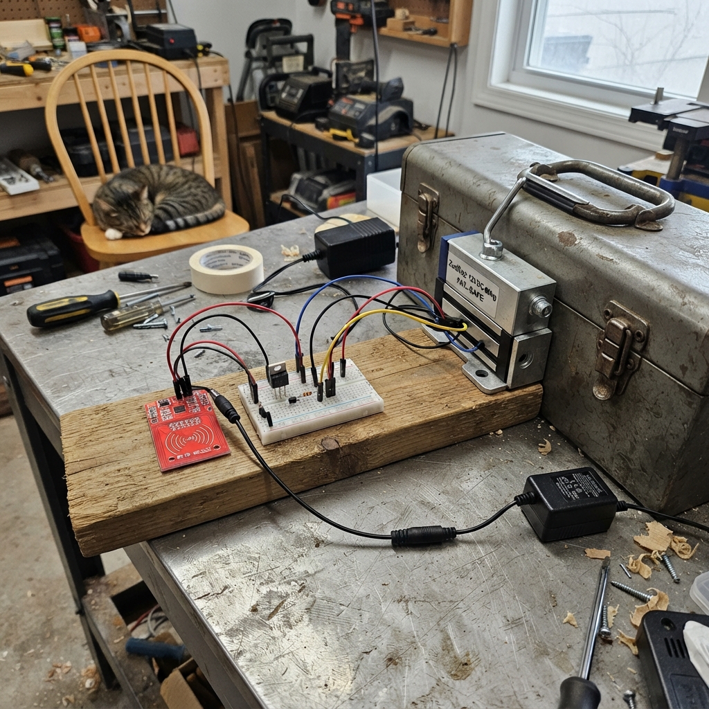
This project builds a secure RFID-controlled toolbox lock using an ESP32 microcontroller and MFRC522 card reader to grant or deny access based on enrolled RFID cards. The 12V fail-safe magnetic lock is driven by a MOSFET circuit that safely handles the high current draw, with a flyback diode protecting against voltage spikes when the lock de-energizes.
The guide provides a complete wiring diagram, parts list, and step-by-step assembly instructions for mounting the reader, building the lock driver circuit, and connecting the 12V power supply. The included firmware handles card enrollment, access control logic, and serial commands for managing approved cards stored in the ESP32's non-volatile memory.
Wiring diagram
Gather all the parts
Assemble it in 5 steps
1. Check the selected hardware
This build uses an ESP32 DevKit v1, RC522 13.56 MHz reader and ZudSec ZDL-60 12V power-to-lock magnet. Use a compatible RFID card. Keep all power disconnected while wiring.
- Do not use this wiring or behavior for a power-to-unlock solenoid latch or a 24V lock. RFID UID matching is cloneable and is not high-security protection.
2. Connect the card reader
VCC to 3V3 (power), GND to GND, SCK to GPIO18 (clock), MOSI to GPIO23 (data to reader), MISO to GPIO19 (data from reader), SDA to GPIO21 (select), RST to GPIO22 (reset). Leave IRQ unconnected.
- Never apply 5V to this reader. Mount its antenna outside the metal toolbox, on a nonmetal spacer; metal reduces reading range.
3. Assemble the lock driver
Use the AO3400A on a labeled SOT-23 adapter for hand wiring. Gate is pin 1, source pin 2, drain pin 3. GPIO25 goes through the 220 ohm resistor to gate. Connect the 100k resistor between gate and ground. Source goes to ground; drain goes to lock minus.
- Solder and insulate the driver connections. Verify the adapter labels; do not guess orientation.
4. Protect and power the lock
Connect adapter +12V to lock plus. Connect the diode across the lock: striped end to plus, unstriped end to minus/drain. Adapter negative joins ESP32 ground. ESP32 receives power only through USB; the 12V positive never goes to the board.
- Reversing the diode shorts the supply when switched on. Use a regulated short-circuit-protected 12V adapter and insulated terminals. Never work on mains wiring.
5. Mount and test with lid open
Fix the magnet to the toolbox body and its matching plate to the lid using the supplied mounting instructions. Align their faces fully. First test with the lid open and fingers clear. With USB powered and the reader responding the magnet energizes. The approved card removes power for five seconds, then the magnet energizes again; there is no lid-position sensor.
- Power loss or ESP32 reset releases this lock. It is not theft-proof. Keep a way to disconnect power accessible. The magnet can become warm during continuous use.
Review all connections
1. Connections between "reader" and "ESP32"
2. Connections between "gate" and "ESP32"
3. Connections between "pulldown" and "ESP32"
4. Connections between "driver" and "ESP32"
5. Connections between "supply" and "ESP32"
6. Connections between "flyback" and "ESP32"
Deploy the firmware
#include <Arduino.h>
#include <SPI.h>
#include <MFRC522.h>
#include <Preferences.h>

constexpr uint8_t LOCK_PIN=25, CS_PIN=21, RESET_PIN=22;
MFRC522 reader(CS_PIN, RESET_PIN);
Preferences prefs;
byte approved[10];
size_t approvedSize=0;
bool enrolling=false, released=false, readerOK=false;
uint32_t enrollUntil=0, releaseUntil=0, lastScan=0;
void setup() {
  digitalWrite(LOCK_PIN, LOW);
  pinMode(LOCK_PIN, OUTPUT);
  Serial.begin(115200);
  prefs.begin("toolbox", false);
  approvedSize=prefs.getBytesLength("uid");
  if (approvedSize>0 && approvedSize<=sizeof(approved)) prefs.getBytes("uid",approved,approvedSize);
  else approvedSize=0;
  SPI.begin(18,19,23,CS_PIN);
  reader.PCD_Init();
  byte v=reader.PCD_ReadRegister(MFRC522::VersionReg);
  readerOK=(v!=0 && v!=255);
  if(!readerOK) { Serial.println("RFID reader not responding. Lock left released. Check wiring and restart."); return; }
  digitalWrite(LOCK_PIN,HIGH);
  Serial.println("Smart Tool Box ready. Send E in serial monitor to enroll/replace your one approved card within 15 seconds.");
  Serial.println(approvedSize ? "Approved card loaded." : "No card enrolled. Send E to begin.");
}
void loop() {
  uint32_t now=millis();
  if (released && (int32_t)(now-releaseUntil)>=0) {
    digitalWrite(LOCK_PIN,HIGH); released=false; Serial.println("Lock energized.");
  }
  while(Serial.available()) {
    char c=Serial.read();
    if(readerOK && (c=='E' || c=='e')) { enrolling=true; enrollUntil=now+15000; Serial.println("Present intended card within 15 seconds."); }
  }
  if(enrolling && (int32_t)(now-enrollUntil)>=0) { enrolling=false; Serial.println("Enrollment timed out."); }
  if(!readerOK || now-lastScan<100) return;
  lastScan=now;
  if(!reader.PICC_IsNewCardPresent() || !reader.PICC_ReadCardSerial()) return;
  if(enrolling) {
    if(reader.uid.size>0 && reader.uid.size<=sizeof(approved)) {
      size_t written=prefs.putBytes("uid",reader.uid.uidByte,reader.uid.size);
      if(written==reader.uid.size) {
        approvedSize=reader.uid.size;
        memcpy(approved,reader.uid.uidByte,approvedSize);
        Serial.println("Card saved. Remove it and tap again to unlock.");
      } else Serial.println("Save failed; restart before retrying.");
    }
    enrolling=false;
  } else {
    bool match=approvedSize>0 && approvedSize==reader.uid.size && memcmp(approved,reader.uid.uidByte,approvedSize)==0;
    if(match) { digitalWrite(LOCK_PIN,LOW); released=true; releaseUntil=now+5000; Serial.println("Access granted: released for 5 seconds."); }
    else Serial.println("Access denied.");
  }
  reader.PICC_HaltA();
  reader.PCD_StopCrypto1();
}
Remix this project
Make it yours in one click
Open a full copy of this project in your own Schematik workspace, diagram, code, parts, and assembly steps included. Swap the sensor, add features, or redesign the whole thing with AI. The author's original stays untouched.