Community project
Solar-Powered Plant Watering
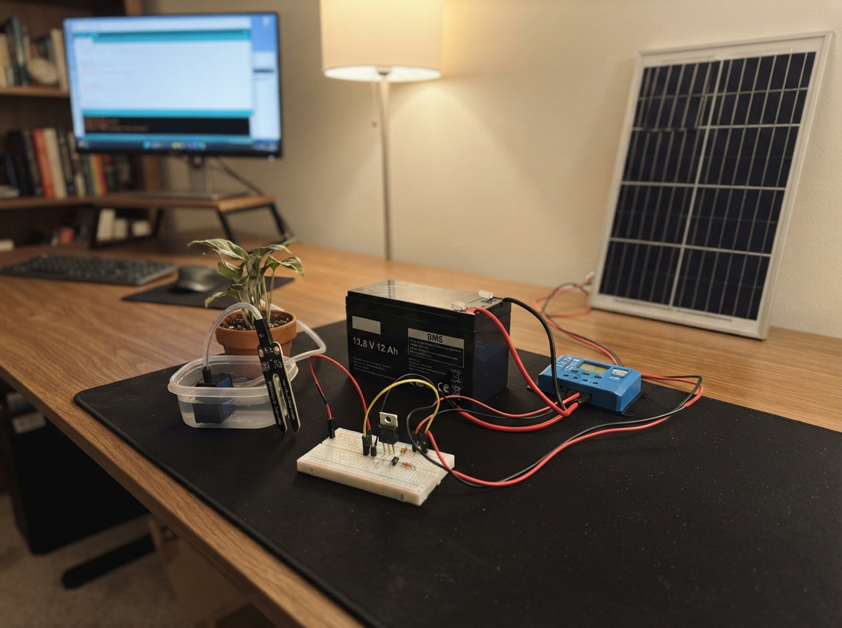
This solar-powered plant watering system automatically waters plants based on soil moisture levels, powered entirely by a 12.8 V LiFePO4 battery charged by a 30 W solar panel. The ESP32 microcontroller reads a capacitive soil moisture sensor and controls a 12 V submersible pump via a MOSFET driver, with battery voltage monitoring and an OLED display for status feedback.
The guide provides a complete wiring diagram, parts list, and step-by-step assembly instructions for building the system with proper protection circuits including a fuse, flyback diode, and solar charge controller. Customizable watering thresholds and intervals are configured through a rotary encoder, and the firmware implements low-power sleep modes to extend battery life between soil checks.
Wiring diagram

Gather all the parts
Assemble it in 10 steps
1. Mount the battery and solar controller
Put the 12.8 V LiFePO4 battery and solar controller in a dry enclosure well above the nutrient tank. Connect battery BAT+ to controller BAT+ (battery power) and battery BAT- to controller BAT- (battery ground).
- Connect the battery before the panel so the controller can recognize the 12 V LiFePO4 system.
- Do not let a metal tool bridge the battery terminals; the battery can deliver enough current to heat wires or cause a fire.
2. Connect the solar panel
Cover the panel or keep it out of sunlight while wiring it. Connect panel PV+ to controller PV+ (charging power) and panel PV- to controller PV- (charging ground).
- Place the panel where it will not be shaded by plants, rails, or tubing.
- Do not connect the panel straight to the battery or ESP32; changing sunlight can create an unsafe voltage.
3. Wire the protected pump circuit
Connect controller LOAD+ to fuse holder IN (pump power), fuse holder OUT to pump PUMP+ (pump power), pump PUMP- to MOSFET DRAIN (switched pump wire), and MOSFET SOURCE to controller LOAD- (ground). Connect the flyback diode unstriped end to MOSFET DRAIN and its striped end to pump PUMP+ (pump protection).
- Choose a fuse just above the pump's measured normal current, with a maximum of 5 A.
- Make sure the diode stripe goes to pump positive; reversing it can short the supply when the pump runs.
4. Wire the pump-control parts
Connect ESP32 GPIO25 to one leg of the 220 Ω resistor (control signal), and connect its other leg to the MOSFET GATE (pump-control signal). Connect one leg of the 10 kΩ resistor to that same GATE point and its other leg to GND (keeps the pump off at startup).
- For a typical IRLZ44N with its label facing you and legs down, the legs are Gate, Drain, Source from left to right; check your actual part marking.
- Never connect the ESP32 directly to a 12 V pump wire; 12 V can permanently damage the board.
5. Set up the ESP32 power converter
With the ESP32 disconnected, use a meter to adjust the buck converter output to exactly 5.0 V. Connect controller LOAD+ to buck VIN+ (input power), controller LOAD- to buck VIN- (input ground), buck VOUT+ to ESP32 VIN or 5V (board power), and buck VOUT- to ESP32 GND (ground).
- The pump circuit and ESP32 must share the controller LOAD- ground so the pump-control signal has a return path.
- Do not connect the 12.8 V controller output directly to ESP32 VIN or 5V; it can destroy the ESP32.
6. Connect the growing-medium sensor
Connect sensor VCC to ESP32 3V3 (power), sensor GND to ESP32 GND (ground), and sensor AOUT to ESP32 GPIO34 (moisture signal). Keep the connector dry and put only the sensing end into the growing medium.
- For hydroponics, use this reading as a starting point only; timed watering or a float switch is often more dependable than a soil-style reading.
- Do not swap VCC and GND; swapped power can damage the sensor.
7. Wire the OLED screen
Connect OLED VCC to ESP32 3V3 (power), OLED GND to ESP32 GND (ground), OLED SDA to GPIO21 (screen data), and OLED SCL to GPIO22 (screen clock). Mount the screen where you can read it without opening the wet equipment area.
- This 3.3 V OLED connects safely to the ESP32 without the signal-voltage converter the old 5 V LCD needed.
- Keep the OLED board and its connections dry; splashed nutrient solution can corrode or short the pins.
8. Wire the rotary control knob
Connect encoder VCC to ESP32 3V3 (power), encoder GND to ESP32 GND (ground), encoder CLK to GPIO16 (turning signal), encoder DT to GPIO17 (turn direction signal), and encoder SW to GPIO33 (push-button signal).
- Turn the knob to change a value and press the knob to move to the next setting. The built-in press switch means no separate buttons are needed.
- Power this encoder from 3.3 V, not 5 V, so its signal wires cannot send an unsafe voltage into the ESP32.
9. Add the battery-voltage reading resistors
Connect one leg of the 100 kΩ resistor to controller LOAD+ (battery voltage signal). Join its other leg to one leg of the 27 kΩ resistor and to ESP32 GPIO35 (safe battery-reading signal). Connect the remaining leg of the 27 kΩ resistor to ESP32 GND (ground).
- These two resistors make the 12–14.6 V battery line safe for the ESP32 to measure. The OLED shows the result as Battery followed by volts.
- Do not connect controller LOAD+ directly to GPIO35; the battery voltage is far above the ESP32's safe 3.3 V input limit.
10. Test with water safely contained
Put the pump inlet in a bucket of clean water and direct its outlet back into the bucket. Apply battery power, check that the OLED shows a sensible battery voltage, then press the knob to enter settings. Turn to change a value, and press to go to the next page and save after the final page.
- The pages set the dry sensor reading, pump run time, and minimum minutes between pump runs. Test each setting before connecting the hydroponic tubing.
- Keep USB leads, the ESP32, and all low-voltage electronics away from water. If a wire becomes warm, disconnect the battery immediately.
Review all connections
1. Connections between "soil_sensor" and "ESP32"
2. Connections between "solar_panel_30w" and "ESP32"
3. Connections between "lifepo4_battery" and "ESP32"
4. Connections between "lifepo4_solar_controller" and "ESP32"
5. Connections between "pump_fuse" and "ESP32"
6. Connections between "pump" and "ESP32"
7. Connections between "pump_mosfet" and "ESP32"
8. Connections between "gate_resistor" and "ESP32"
9. Connections between "gate_pulldown" and "ESP32"
10. Connections between "flyback_diode" and "ESP32"
11. Connections between "esp32_buck" and "ESP32"
12. Connections between "battery_divider_top" and "ESP32"
13. Connections between "battery_divider_bottom" and "ESP32"
14. Connections between "status_oled" and "ESP32"
15. Connections between "menu_encoder" and "ESP32"
Deploy the firmware
#include <Arduino.h>
#include <Wire.h>
#include <esp_sleep.h>
#include <Preferences.h>
#include <Adafruit_GFX.h>
#include <Adafruit_SSD1306.h>


// Forward declarations
int readAverage(int pin);
float readBatteryVoltage();
bool encoderPressed();
void drawStatus();
void drawSetting(uint8_t page);
void saveSettings();
void settingsMode();
void sleepUntilNextCheck();

constexpr int SOIL_PIN = 34;
constexpr int BATTERY_PIN = 35;
constexpr int PUMP_PIN = 25;
constexpr int ENCODER_CLK_PIN = 16;
constexpr int ENCODER_DT_PIN = 17;
constexpr int ENCODER_SW_PIN = 33;
constexpr int SDA_PIN = 21;
constexpr int SCL_PIN = 22;
constexpr uint8_t OLED_ADDRESS = 0x3C;
constexpr int SCREEN_WIDTH = 128;
constexpr int SCREEN_HEIGHT = 64;
constexpr float DIVIDER_RATIO = 127.0f / 27.0f;
constexpr uint32_t CHECK_SECONDS = 300;
constexpr int DEFAULT_DRY_THRESHOLD = 2500;
constexpr uint32_t DEFAULT_WATER_MS = 8000;
constexpr uint32_t DEFAULT_GAP_MINUTES = 60;

Adafruit_SSD1306 display(SCREEN_WIDTH, SCREEN_HEIGHT, &Wire, -1);
Preferences preferences;
int dryThreshold;
uint32_t waterTimeMs;
uint32_t gapMinutes;
RTC_DATA_ATTR uint32_t secondsSinceWater = DEFAULT_GAP_MINUTES * 60;
RTC_DATA_ATTR bool soilWasDry = false;

int readAverage(int pin) {
  uint32_t total = 0;
  for (int i = 0; i < 12; ++i) {
    total += analogRead(pin);
    delay(10);
  }
  return total / 12;
}

float readBatteryVoltage() {
  return (readAverage(BATTERY_PIN) / 4095.0f) * 3.3f * DIVIDER_RATIO;
}

bool encoderPressed() {
  if (digitalRead(ENCODER_SW_PIN) != LOW) return false;
  delay(25);
  if (digitalRead(ENCODER_SW_PIN) != LOW) return false;
  while (digitalRead(ENCODER_SW_PIN) == LOW) delay(5);
  return true;
}

void drawStatus() {
  const int soil = readAverage(SOIL_PIN);
  const float battery = readBatteryVoltage();
  display.clearDisplay();
  display.setTextSize(1);
  display.setTextColor(SSD1306_WHITE);
  display.setCursor(0, 0);
  display.print("Hydroponics ready");
  display.setCursor(0, 18);
  display.print("Battery: ");
  display.print(battery, 1);
  display.println(" V");
  display.print("Sensor:  ");
  display.println(soil);
  display.setCursor(0, 52);
  display.print("Press knob: settings");
  display.display();
}

void drawSetting(uint8_t page) {
  display.clearDisplay();
  display.setTextSize(1);
  display.setTextColor(SSD1306_WHITE);
  display.setCursor(0, 0);
  if (page == 0) {
    display.println("Dry threshold");
    display.setTextSize(2); display.println(dryThreshold);
  } else if (page == 1) {
    display.println("Pump seconds");
    display.setTextSize(2); display.println(waterTimeMs / 1000UL);
  } else {
    display.println("Minimum gap min");
    display.setTextSize(2); display.println(gapMinutes);
  }
  display.setTextSize(1);
  display.setCursor(0, 52);
  display.print("Turn=change Press=next");
  display.display();
}

void saveSettings() {
  preferences.putInt("dry", dryThreshold);
  preferences.putUInt("water", waterTimeMs);
  preferences.putUInt("gap", gapMinutes);
}

void settingsMode() {
  uint8_t page = 0;
  int lastClk = digitalRead(ENCODER_CLK_PIN);
  uint32_t lastAction = millis();
  drawSetting(page);

  while (millis() - lastAction < 60000UL) {
    const int clk = digitalRead(ENCODER_CLK_PIN);
    if (clk != lastClk && clk == LOW) {
      const bool clockwise = digitalRead(ENCODER_DT_PIN) != clk;
      if (page == 0) dryThreshold = constrain(dryThreshold + (clockwise ? 50 : -50), 0, 4000);
      if (page == 1) waterTimeMs = constrain(waterTimeMs + (clockwise ? 1000 : -1000), 1000, 60000);
      if (page == 2) gapMinutes = constrain(gapMinutes + (clockwise ? 5 : -5), 5, 720);
      drawSetting(page);
      lastAction = millis();
    }
    lastClk = clk;

    if (encoderPressed()) {
      lastAction = millis();
      if (page == 2) {
        saveSettings();
        display.clearDisplay();
        display.setTextSize(1); display.setTextColor(SSD1306_WHITE);
        display.setCursor(0, 24); display.print("Settings saved");
        display.display();
        delay(1000);
        return;
      }
      ++page;
      drawSetting(page);
    }
    delay(2);
  }
  saveSettings();
}

void sleepUntilNextCheck() {
  digitalWrite(PUMP_PIN, LOW);
  display.clearDisplay();
  display.display();
  display.ssd1306_command(SSD1306_DISPLAYOFF);
  esp_sleep_enable_timer_wakeup(static_cast<uint64_t>(CHECK_SECONDS) * 1000000ULL);
  esp_sleep_enable_ext0_wakeup(static_cast<gpio_num_t>(ENCODER_SW_PIN), LOW);
  esp_deep_sleep_start();
}

void setup() {
  pinMode(PUMP_PIN, OUTPUT);
  digitalWrite(PUMP_PIN, LOW);
  pinMode(ENCODER_CLK_PIN, INPUT_PULLUP);
  pinMode(ENCODER_DT_PIN, INPUT_PULLUP);
  pinMode(ENCODER_SW_PIN, INPUT_PULLUP);
  analogReadResolution(12);
  analogSetPinAttenuation(BATTERY_PIN, ADC_11db);
  Wire.begin(SDA_PIN, SCL_PIN);
  display.begin(SSD1306_SWITCHCAPVCC, OLED_ADDRESS);
  preferences.begin("hydro", false);
  dryThreshold = preferences.getInt("dry", DEFAULT_DRY_THRESHOLD);
  waterTimeMs = preferences.getUInt("water", DEFAULT_WATER_MS);
  gapMinutes = preferences.getUInt("gap", DEFAULT_GAP_MINUTES);

  if (esp_sleep_get_wakeup_cause() == ESP_SLEEP_WAKEUP_EXT0) {
    settingsMode();
    sleepUntilNextCheck();
  }

  const int soil = readAverage(SOIL_PIN);
  if (soil >= dryThreshold) soilWasDry = true;
  else if (soil <= dryThreshold - 100) soilWasDry = false;

  if (soilWasDry && secondsSinceWater >= gapMinutes * 60UL) {
    display.clearDisplay();
    display.setTextSize(1); display.setTextColor(SSD1306_WHITE);
    display.setCursor(0, 24); display.print("Pump running...");
    display.display();
    digitalWrite(PUMP_PIN, HIGH);
    delay(waterTimeMs);
    digitalWrite(PUMP_PIN, LOW);
    secondsSinceWater = 0;
  } else {
    secondsSinceWater = min(86400UL, secondsSinceWater + CHECK_SECONDS);
  }

  drawStatus();
  delay(3000);
  sleepUntilNextCheck();
}

void loop() {}
Remix this project
Make it yours in one click
Open a full copy of this project in your own Schematik workspace — diagram, code, parts, and assembly steps included. Swap the sensor, add features, or redesign the whole thing with AI. The author's original stays untouched.
Related projects

Create A Complete Electrical Schematic Esp32 Sma
ESP32 · September 17, 2026Ayansh Agrawal
ESP32 Kare Ekran Projeleri
ESP32 · September 16, 2026Seref Ai
Component Qty --------------------------- ------
ESP32 · September 16, 2026Yathartha Chakrawal