Community project
Split-Flap Digit Controller
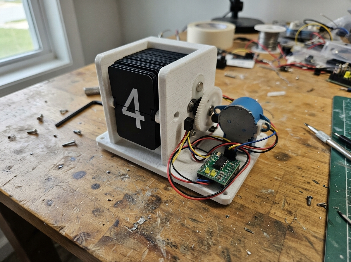
This guide builds a split-flap digit controller that rotates a mechanical display wheel to show any digit 0-9 on demand. The system uses a 28BYJ-48 stepper motor driven by a ULN2003 board, with a Honeywell Hall-effect sensor and small neodymium magnet for reliable homing. The ConnorQuist split-flap mechanism provides the printed wheel with 40 flaps, each precisely indexed by the stepper motor.
Following this guide, makers will receive a complete wiring diagram, parts list with sourcing links, and ESP32 firmware that handles motor control, sensor calibration, and digit selection via serial commands. The assembly steps cover mounting the motor and sensor to the printed mechanism, calibrating the home position, and testing individual digit movements before integration into larger display projects.
Wiring diagram

Gather all the parts
Assemble it in 5 steps
1.
2.
3.
4.
5.
Review all connections
1. Connections between "uln2003-stepper-driver-1" and "ESP32"
2. Connections between "28byj-48-stepper-1" and "ESP32"
3. Connections between "ky-035-hall-sensor-1" and "ESP32"
Deploy the firmware
#include <Arduino.h>
#include <Stepper.h>

#define STEPS_PER_REV 2048
#define MOTOR_IN1 16
#define MOTOR_IN2 17
#define MOTOR_IN3 18
#define MOTOR_IN4 19
#define HALL_PIN 34
#define HOME_THRESHOLD 2600
#define FLAP_COUNT 40
#define FIRST_DIGIT_FLAP 27
#define STEPS_PER_FLAP (STEPS_PER_REV / FLAP_COUNT)

Stepper flapMotor(STEPS_PER_REV, MOTOR_IN1, MOTOR_IN3, MOTOR_IN2, MOTOR_IN4);
int currentFlap = 0;
int currentDigit = -1;
bool demoMode = false;
unsigned long lastDemoStep = 0;

bool magnetDetected() { return analogRead(HALL_PIN) > HOME_THRESHOLD; }
void stepForward(int steps) { flapMotor.step(-steps); }
void homeWheel() {
  Serial.println("Homing split-flap wheel...");
  for (int i = 0; i < STEPS_PER_REV + 300; i += 4) {
    if (magnetDetected()) {
      stepForward(5);
      currentFlap = 0;
      currentDigit = -1;
      Serial.println("Home magnet found at blank flap");
      return;
    }
    stepForward(4);
  }
  Serial.println("Home magnet not found. Check sensor alignment.");
}
void moveToFlap(int targetFlap) {
  targetFlap = constrain(targetFlap, 0, FLAP_COUNT - 1);
  if (targetFlap < currentFlap) homeWheel();
  stepForward((targetFlap - currentFlap) * STEPS_PER_FLAP);
  currentFlap = targetFlap;
}
void showDigit(int targetDigit) {
  targetDigit = constrain(targetDigit, 0, 9);
  moveToFlap(FIRST_DIGIT_FLAP + targetDigit);
  currentDigit = targetDigit;
  Serial.printf("Showing digit %d on source flap %d\n", currentDigit, currentFlap);
}
void printHelp() { Serial.println("Commands: ? help, r Hall reading, h home, 0-9 digit, n next, d demo"); }
void handleCommand(char command) {
  if (command >= '0' && command <= '9') { demoMode = false; showDigit(command - '0'); return; }
  switch (command) {
    case '?': printHelp(); break;
    case 'r': Serial.printf("Hall reading: %d\n", analogRead(HALL_PIN)); break;
    case 'h': demoMode = false; homeWheel(); break;
    case 'n': demoMode = false; showDigit(currentDigit < 0 ? 0 : (currentDigit + 1) % 10); break;
    case 'd': demoMode = !demoMode; lastDemoStep = millis(); Serial.printf("Demo %s\n", demoMode ? "on" : "off"); break;
    case '\n': case '\r': break;
    default: Serial.println("Unknown command. Send ? for help.");
  }
}
void setup() {
  Serial.begin(115200); analogReadResolution(12); pinMode(HALL_PIN, INPUT); flapMotor.setSpeed(12); delay(500); homeWheel(); printHelp();
}
void loop() {
  while (Serial.available()) handleCommand((char)Serial.read());
  if (demoMode && millis() - lastDemoStep >= 1200) { showDigit(currentDigit < 0 ? 0 : (currentDigit + 1) % 10); lastDemoStep = millis(); }
}
Remix this project
Make it yours in one click
Open a full copy of this project in your own Schematik workspace — diagram, code, parts, and assembly steps included. Swap the sensor, add features, or redesign the whole thing with AI. The author's original stays untouched.