Community project
T I S Mua Th M 1 Nrf24l01
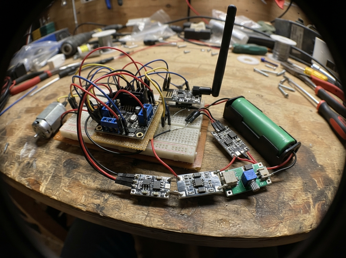
Build a wireless-controlled robot vehicle powered by lithium-ion batteries and driven by DC gearmotors. This guide covers a complete mecanum-wheel drive system controlled via nRF24L01+ radio modules, with an Arduino Uno receiving motor commands from a handheld Arduino Nano controller.
The project includes a detailed parts list, wiring diagram showing motor controller connections, battery management setup with BMS and charger, and step-by-step assembly instructions. Firmware for both the vehicle receiver and remote transmitter handles joystick input, radio communication, and motor speed control through PWM and shift registers.
Wiring diagram

Gather all the parts
Assemble it in 7 steps
1. Lắp bánh và mô-tơ
Gắn bốn mô-tơ vào khung xe và gắn bánh mecanum theo đúng cặp trái/phải. Gọi các vị trí là trước-trái, trước-phải, sau-trái và sau-phải để khớp với sơ đồ.
- Đừng cấp điện khi bánh còn chạm bàn; xe có thể chạy bất ngờ.
2. Nối mô-tơ với hai mạch L298N
Mạch l298n_front: OUT1 và OUT2 tới hai dây mô-tơ trước-trái, OUT3 và OUT4 tới hai dây mô-tơ trước-phải. Mạch l298n_rear: OUT1/OUT2 tới sau-trái, OUT3/OUT4 tới sau-phải. Nếu một bánh quay ngược trong lúc thử, tắt nguồn rồi đổi chéo đúng hai dây của bánh đó.
- Đây là các dây công suất; dùng dây lớn hơn dây tín hiệu.
3. Lắp bộ pin có bảo vệ
Lắp ba cell cùng loại và cùng tình trạng thành pack 3S: cell 1 âm tới B-, điểm nối cell 1 dương/cell 2 âm tới B1, điểm nối cell 2 dương/cell 3 âm tới B2, và cell 3 dương tới B+. Chỉ lấy điện cho xe ở P+ và P- của BMS.
- Không trộn cell cũ mới hoặc khác dung lượng — pin có thể nóng, hỏng hoặc cháy.
- Chỉ cắm adapter đúng loại vào cổng DC IN của bộ sạc 3S.
4. Nối nguồn xe
P+ của BMS đi tới VS của cả hai L298N và VIN+ của buck_5v; P- đi tới GND của cả hai L298N và VIN- của buck_5v. Chỉnh buck_5v đúng 5,0 V trước khi nối Uno hay radio. VOUT+ là 5 V (nguồn), VOUT- là GND (đường về).
- Đo đầu ra bộ hạ áp trước; điện áp cao hơn 5 V có thể làm hỏng Uno và radio.
5. Nối Uno, radio và mạch điều khiển chiều
Gắn Uno 5 V/GND vào nguồn 5 V/GND chung. D3/D5/D6/D9 lần lượt tới ENA/ENB của L298N trước và ENA/ENB của L298N sau (tốc độ). Mạch 74HC595: A1 tới SER, A2 tới SRCLK, A3 tới RCLK, VCC tới 5 V, GND và OE tới GND; Q0–Q7 đi lần lượt tới IN1–IN4 của L298N trước rồi IN1–IN4 của L298N sau (chiều quay).
- Tất cả GND của Uno, L298N, radio và bộ hạ áp phải nối chung; nếu không xe sẽ điều khiển thất thường.
6. Cấp nguồn và nối radio 3,3 V
Mỗi nRF24 dùng bộ ổn áp 3,3 V riêng và tụ 47 µF: chân dài tụ tới VCC, chân sọc tới GND. Không bao giờ nối VCC radio vào 5 V. Nối các dây CE, CSN, SCK, MOSI qua mạch đổi mức; MISO từ radio xe tới D12 Uno.
- Đảo VCC/GND hoặc đưa 5 V vào radio sẽ làm hỏng nRF24.
7. Lắp tay điều khiển
Nối joystick_drive: VCC tới 5 V, GND tới GND, VRx tới A0 Nano và VRy tới A1 Nano. Nối joystick_turn: VCC tới 5 V, GND tới GND, VRx tới A2 Nano. Cấp nguồn Nano bằng USB 5 V khi thử.
- Dùng joystick_drive để tiến/lùi và ngang; joystick_turn để xoay tại chỗ.
Review all connections
1. Connections between "battery_cell_1" and "Arduino"
2. Connections between "battery_cell_2" and "Arduino"
3. Connections between "battery_cell_3" and "Arduino"
4. Connections between "bms_3s" and "Arduino"
5. Connections between "charger_3s" and "Arduino"
6. Connections between "buck_5v" and "Arduino"
7. Connections between "l298n_front" and "Arduino"
8. Connections between "l298n_rear" and "Arduino"
9. Connections between "regulator_3v3_vehicle" and "Arduino"
10. Connections between "nrf_receiver" and "Arduino"
11. Connections between "cap_vehicle_radio" and "Arduino"
12. Connections between "level_shifter_vehicle" and "Arduino"
13. Connections between "shift_register" and "Arduino"
14. Connections between "motor_front_left" and "Arduino"
15. Connections between "motor_front_right" and "Arduino"
16. Connections between "motor_rear_left" and "Arduino"
17. Connections between "motor_rear_right" and "Arduino"
18. Connections between "nano_remote" and "Arduino"
19. Connections between "joystick_drive" and "Arduino"
20. Connections between "joystick_turn" and "Arduino"
21. Connections between "regulator_3v3_remote" and "Arduino"
22. Connections between "nrf_transmitter" and "Arduino"
23. Connections between "cap_remote_radio" and "Arduino"
24. Connections between "level_shifter_remote" and "Arduino"
Deploy the firmware
#include <Arduino.h>
#include <SPI.h>
#include <RF24.h>

struct CommandPacket {
  int16_t x;       // left/right strafe
  int16_t y;       // forward/reverse
  int16_t turn;    // rotate left/right
  uint8_t sequence;
};


// Forward declarations
int clampMotor(int value);
void setDirectionBits(uint8_t &bits, uint8_t motorIndex, int value);
void writeDirections(uint8_t bits);
void setSpeeds(int fl, int fr, int rl, int rr);
void stopAllMotors();
void driveMecanum(const CommandPacket &command);

const uint8_t NRF_CE_PIN = A0;
const uint8_t NRF_CSN_PIN = 10;
const uint8_t FL_EN = 3;
const uint8_t FR_EN = 5;
const uint8_t RL_EN = 6;
const uint8_t RR_EN = 9;
const uint8_t SHIFT_DATA = A1;
const uint8_t SHIFT_CLOCK = A2;
const uint8_t SHIFT_LATCH = A3;
const byte RADIO_ADDRESS[6] = "MEC01";
const unsigned long RADIO_TIMEOUT_MS = 300;

RF24 radio(NRF_CE_PIN, NRF_CSN_PIN);
unsigned long lastPacketMs = 0;

int clampMotor(int value) {
  if (value > 255) return 255;
  if (value < -255) return -255;
  return value;
}

void setDirectionBits(uint8_t &bits, uint8_t motorIndex, int value) {
  const uint8_t forwardBit = motorIndex * 2;
  const uint8_t reverseBit = forwardBit + 1;
  if (value > 0) bits |= _BV(forwardBit);
  else if (value < 0) bits |= _BV(reverseBit);
}

void writeDirections(uint8_t bits) {
  digitalWrite(SHIFT_LATCH, LOW);
  shiftOut(SHIFT_DATA, SHIFT_CLOCK, MSBFIRST, bits);
  digitalWrite(SHIFT_LATCH, HIGH);
}

void setSpeeds(int fl, int fr, int rl, int rr) {
  analogWrite(FL_EN, abs(clampMotor(fl)));
  analogWrite(FR_EN, abs(clampMotor(fr)));
  analogWrite(RL_EN, abs(clampMotor(rl)));
  analogWrite(RR_EN, abs(clampMotor(rr)));
}

void stopAllMotors() {
  setSpeeds(0, 0, 0, 0);
  writeDirections(0);
}

void driveMecanum(const CommandPacket &command) {
  int fl = clampMotor(command.y + command.x + command.turn);
  int fr = clampMotor(command.y - command.x - command.turn);
  int rl = clampMotor(command.y - command.x + command.turn);
  int rr = clampMotor(command.y + command.x - command.turn);

  uint8_t directions = 0;
  setDirectionBits(directions, 0, fl); // Q0/Q1 -> front-left IN1/IN2
  setDirectionBits(directions, 1, fr); // Q2/Q3 -> front-right IN3/IN4
  setDirectionBits(directions, 2, rl); // Q4/Q5 -> rear-left IN1/IN2
  setDirectionBits(directions, 3, rr); // Q6/Q7 -> rear-right IN3/IN4
  writeDirections(directions);
  setSpeeds(fl, fr, rl, rr);
}

void setup() {
  pinMode(FL_EN, OUTPUT); pinMode(FR_EN, OUTPUT);
  pinMode(RL_EN, OUTPUT); pinMode(RR_EN, OUTPUT);
  pinMode(SHIFT_DATA, OUTPUT); pinMode(SHIFT_CLOCK, OUTPUT); pinMode(SHIFT_LATCH, OUTPUT);
  stopAllMotors();

  radio.begin();
  radio.setPALevel(RF24_PA_LOW);
  radio.setDataRate(RF24_250KBPS);
  radio.setChannel(108);
  radio.openReadingPipe(1, RADIO_ADDRESS);
  radio.startListening();
}

void loop() {
  if (radio.available()) {
    CommandPacket command;
    while (radio.available()) radio.read(&command, sizeof(command));
    lastPacketMs = millis();
    driveMecanum(command);
  }
  if (millis() - lastPacketMs > RADIO_TIMEOUT_MS) stopAllMotors();
}
Remix this project
Make it yours in one click
Open a full copy of this project in your own Schematik workspace — diagram, code, parts, and assembly steps included. Swap the sensor, add features, or redesign the whole thing with AI. The author's original stays untouched.
Related projects
Two-Way Traffic Control
Arduino · September 30, 2026Gebe Undang Tabanas
Bueno Entonces Creamos El Control Tmb O Lo
Arduino · September 30, 2026nicolas onguino
Server Room Security System
Arduino · September 30, 2026Mark Christian S. Maraviles