Community project
Temperature Humidity Trend Display
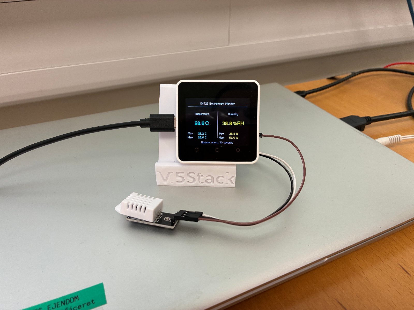
This project builds a real-time temperature and humidity monitor using an ESP32 and DHT22 sensor. The display shows current readings alongside minimum and maximum values tracked over time, updating every 30 seconds to give a clear picture of environmental trends.
The guide includes a complete wiring diagram, parts list, and ready-to-deploy firmware. Assembly takes just minutes: identify the DHT22 pins, make three connections (power, ground, and data), then upload the code to start monitoring.
Wiring diagram

Gather all the parts
Assemble it in 4 steps
1. Power down and identify the DHT22 pins
Disconnect the M5Stack Core2 from USB. With the DHT22 grille facing you, a bare four-pin DHT22 is normally VCC, DATA, NC, GND from left to right. If yours is on a three-pin breakout board, follow its printed VCC, DATA/OUT, and GND labels.
- A four-pin bare DHT22 needs a 4.7 kΩ to 10 kΩ pull-up resistor between VCC and DATA. Most three-pin breakout boards include this resistor.
- Keep the sensor away from the Core2's warm rear enclosure and direct sunlight for representative readings.
- Use 3.3 V for the DHT22 VCC, not 5 V.
- Confirm the pin order before connecting power; reversing VCC and GND can damage the sensor.
2. Wire power and ground
Connect DHT22 VCC to the Core2 expansion header's 3.3 V pin and DHT22 GND to a GND pin. For a bare four-pin sensor, fit the pull-up resistor from VCC to DATA.
- The sensor and Core2 must share ground.
- Leave the bare sensor's NC pin disconnected.
3. Connect the sensor data line
Connect the DHT22 DATA/OUT pin to GPIO13 on the Core2 expansion header. Do not connect the DATA wire to any other GPIO.
- A three-pin DHT22 breakout generally includes its own DATA pull-up resistor.
- The display history grows from startup until it contains one hour of readings.
- For a bare DHT22, a missing DATA pull-up resistor causes unreliable or failed readings.
4. Power and deploy
Recheck VCC, GND, and GPIO13, then reconnect USB. Use Schematik’s Deploy button to build and flash the project. Live values update every 5 seconds; cyan is temperature and yellow is humidity in the one-hour chart.
- The circular history buffer holds 720 valid samples: one hour at the required 5-second interval.
- A red “DHT22 read failed” message usually indicates wiring, pin-order, or pull-up-resistor trouble.
- History is stored in RAM, so it starts over after reset or power loss.
Review all connections
1. Connections between "dht22_1" and "ESP32"
Deploy the firmware
#include <Arduino.h>
#include <M5Unified.h>
#include <DHT.h>
#include <math.h>


// Forward declarations
void drawStaticScreen();
void showReading(float temperature, float humidity);
void takeSample();

constexpr uint8_t DHT_PIN = 13;
constexpr uint8_t DHT_SENSOR_TYPE = DHT22;
constexpr uint32_t SAMPLE_INTERVAL_MS = 30000UL;
constexpr int SCREEN_W = 320;

DHT dht(DHT_PIN, DHT_SENSOR_TYPE);
uint32_t lastSampleMs = 0;
bool haveValidReading = false;
float minTemperature = 0.0f;
float maxTemperature = 0.0f;
float minHumidity = 0.0f;
float maxHumidity = 0.0f;

void drawStaticScreen() {
  M5.Lcd.fillScreen(TFT_BLACK);
  M5.Lcd.setTextColor(TFT_WHITE, TFT_BLACK);
  M5.Lcd.drawCentreString("DHT22 Environment Monitor", SCREEN_W / 2, 18, 2);
  M5.Lcd.drawFastHLine(8, 42, 304, TFT_DARKGREY);

  M5.Lcd.setTextColor(TFT_LIGHTGREY, TFT_BLACK);
  M5.Lcd.drawCentreString("Temperature", 80, 70, 2);
  M5.Lcd.drawCentreString("Humidity", 240, 70, 2);
  M5.Lcd.drawFastVLine(160, 64, 135, TFT_DARKGREY);

  M5.Lcd.setTextColor(TFT_LIGHTGREY, TFT_BLACK);
  M5.Lcd.drawCentreString("Min:", 22, 170, 2);
  M5.Lcd.drawCentreString("Max:", 22, 190, 2);
  M5.Lcd.drawCentreString("Min:", 182, 170, 2);
  M5.Lcd.drawCentreString("Max:", 182, 190, 2);

  M5.Lcd.setTextColor(TFT_DARKGREY, TFT_BLACK);
  M5.Lcd.drawCentreString("Updates every 30 seconds", SCREEN_W / 2, 215, 2);
}

void showReading(float temperature, float humidity) {
  M5.Lcd.fillRect(55, 101, 97, 104, TFT_BLACK);
  M5.Lcd.fillRect(215, 101, 97, 104, TFT_BLACK);

  M5.Lcd.setTextColor(TFT_CYAN, TFT_BLACK);
  M5.Lcd.drawCentreString(String(temperature, 1) + " C", 80, 115, 4);
  M5.Lcd.drawString(String(minTemperature, 1) + " C", 62, 170, 2);
  M5.Lcd.drawString(String(maxTemperature, 1) + " C", 62, 190, 2);

  M5.Lcd.setTextColor(TFT_YELLOW, TFT_BLACK);
  M5.Lcd.drawCentreString(String(humidity, 1) + " %RH", 240, 115, 4);
  M5.Lcd.drawString(String(minHumidity, 1) + " %", 222, 170, 2);
  M5.Lcd.drawString(String(maxHumidity, 1) + " %", 222, 190, 2);
}

void takeSample() {
  const float humidity = dht.readHumidity();
  const float temperature = dht.readTemperature();

  if (isnan(temperature) || isnan(humidity)) {
    M5.Lcd.fillRect(8, 101, 304, 62, TFT_BLACK);
    M5.Lcd.setTextColor(TFT_RED, TFT_BLACK);
    M5.Lcd.drawCentreString("DHT22 read failed", SCREEN_W / 2, 122, 2);
    return;
  }

  if (!haveValidReading) {
    minTemperature = maxTemperature = temperature;
    minHumidity = maxHumidity = humidity;
    haveValidReading = true;
  } else {
    minTemperature = min(minTemperature, temperature);
    maxTemperature = max(maxTemperature, temperature);
    minHumidity = min(minHumidity, humidity);
    maxHumidity = max(maxHumidity, humidity);
  }

  showReading(temperature, humidity);
}

void setup() {
  auto cfg = M5.config();
  M5.begin(cfg);
  M5.Lcd.setRotation(1);
  dht.begin();
  drawStaticScreen();
  takeSample();
  lastSampleMs = millis();
}

void loop() {
  M5.update();
  const uint32_t now = millis();
  if (now - lastSampleMs >= SAMPLE_INTERVAL_MS) {
    lastSampleMs += SAMPLE_INTERVAL_MS;
    takeSample();
  }
}
Remix this project
Make it yours in one click
Open a full copy of this project in your own Schematik workspace — diagram, code, parts, and assembly steps included. Swap the sensor, add features, or redesign the whole thing with AI. The author's original stays untouched.
Related projects

Create A Complete Electrical Schematic Esp32 Sma
ESP32 · September 17, 2026Ayansh Agrawal
ESP32 Kare Ekran Projeleri
ESP32 · September 16, 2026Seref Ai
Component Qty --------------------------- ------
ESP32 · September 16, 2026Yathartha Chakrawal