Community project
Temperature Scale Monitor
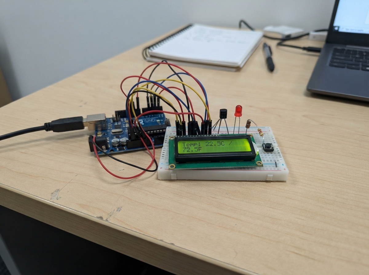
This project builds a temperature monitoring system that reads ambient temperature using an LM35DZ sensor and displays it on a 16x2 LCD screen. The system can switch between Celsius and Fahrenheit scales with a push button, and triggers LED indicators when temperature exceeds a set threshold—useful for thermal monitoring in workshops, server rooms, or environmental control applications.
The guide provides a complete parts list, wiring diagram showing connections between the Arduino Uno, LM35DZ analog sensor, I2C LCD display, status LEDs, and push button control. Assembly steps walk through sensor calibration, LCD initialization via I2C protocol, and firmware installation that handles temperature sampling, display updates, and threshold-based LED alerts.
Wiring diagram

Gather all the parts
Assemble it in 6 steps
1. Desconecta el Mega
Desconecta el cable USB antes de colocar los cables. Usa el Arduino Mega 2560, no el Uno.
- Mover cables con alimentación puede causar un cortocircuito y dañar la placa.
2. Conecta el sensor
Con el LM35DZ de tres patas, cara plana hacia ti y patas hacia abajo: conecta la pata izquierda a 5V (alimentación), la central a A0 (temperatura) y la derecha a GND (tierra). Verifica que tu pieza es el LM35DZ antes de conectar.
- Invertir la alimentación puede dañar el LM35.
3. Conecta la pantalla
En la pantalla con adaptador I2C, conecta VCC a 5V (alimentación), GND a GND (tierra), SDA a D20 (datos) y SCL a D21 (coordinación). No uses A4 y A5: esos eran los pines del Uno.
- El programa admite direcciones 0x27 y 0x3F con el adaptador PCF8574 habitual.
- Si aparecen bloques o no ves letras, gira suavemente el pequeño tornillo del adaptador para ajustar el contraste.
- Intercambiar VCC y GND puede dañar la pantalla.
4. Conecta los dos LED
Conecta D8 a una pata de la resistencia amarilla de 220 Ω (señal); la otra pata va a la pata larga del LED amarillo (positivo). Conecta su pata corta a GND (tierra). Repite con D9, la otra resistencia de 220 Ω y el LED rojo.
- Sin las resistencias puedes dañar los LED y las salidas del Mega.
5. Conecta el pulsador
Conecta una pata del pulsador a D2 (señal) y la otra a GND (tierra), de modo que al presionar una D2 con GND. Si tiene cuatro patas, usa dos que no estén unidas cuando está suelto.
- No hace falta una resistencia externa: el programa activa la que lleva el Mega por dentro.
6. Revisa el montaje
Comprueba que todas las tierras comparten GND y que ninguna pata o cable une 5V con GND. Revisa especialmente la orientación del sensor y los LED antes de conectar el USB.
- El amarillo corresponde a menos de 40 °C; el rojo a 40 °C o más. El pulsador solo cambia la escala mostrada.
Review all connections
1. Connections between "lm35" and "Arduino"
2. Connections between "lcd" and "Arduino"
3. Connections between "res_amarillo" and "Arduino"
4. Connections between "led_amarillo" and "Arduino"
5. Connections between "res_rojo" and "Arduino"
6. Connections between "led_rojo" and "Arduino"
7. Connections between "boton" and "Arduino"
Deploy the firmware
#include <Arduino.h>
#include <Wire.h>
#include <string.h>
#include <stdlib.h>
#include <stdio.h>

const uint8_t LM35_PIN = A0;
const uint8_t LED_AMARILLO_PIN = 8;
const uint8_t LED_ROJO_PIN = 9;
const uint8_t BOTON_PIN = 2;
// Referencia ADC: alimentacion nominal de 5 V del Mega.
const float REFERENCIA_V = 5.0f;
const float LIMITE_C = 40.0f;
// Adaptador PCF8574 habitual: RS=P0, RW=P1, E=P2,
// luz=P3 y D4..D7=P4..P7. RW siempre se mantiene en cero.
uint8_t direccionLCD = 0;
char anterior[2][16];
bool fahrenheit = false;
bool hayLectura = false;
float temperaturaC = 0;
bool botonCrudo = HIGH;
bool botonEstable = HIGH;
unsigned long cambioBoton = 0;
unsigned long ultimaMuestra = 0;
unsigned long ultimaLectura = 0;
uint32_t suma = 0;
uint8_t muestras = 0;

bool responde(uint8_t direccion) {
  Wire.beginTransmission(direccion);
  return Wire.endTransmission() == 0;
}

void salidaLCD(uint8_t valor) {
  Wire.beginTransmission(direccionLCD);
  Wire.write(valor | 0x08); // Luz encendida.
  Wire.endTransmission();
}

void nibbleLCD(uint8_t nibble, bool dato) {
  uint8_t valor = (nibble << 4) | (dato ? 0x01 : 0x00);
  salidaLCD(valor);
  salidaLCD(valor | 0x04);
  delayMicroseconds(1);
  salidaLCD(valor);
  delayMicroseconds(50);
}

void enviarLCD(uint8_t valor, bool dato) {
  nibbleLCD(valor >> 4, dato);
  nibbleLCD(valor & 0x0F, dato);
}

void iniciarLCD() {
  delay(50);
  salidaLCD(0);
  nibbleLCD(3, false);
  delay(5);
  nibbleLCD(3, false);
  delayMicroseconds(150);
  nibbleLCD(3, false);
  nibbleLCD(2, false); // Modo de cuatro bits.
  enviarLCD(0x28, false); // Dos filas, caracteres 5x8.
  enviarLCD(0x08, false); // Pantalla apagada durante el inicio.
  enviarLCD(0x01, false); // Limpiar solo al iniciar.
  delay(2);
  enviarLCD(0x06, false); // Avanzar el cursor sin desplazar.
  enviarLCD(0x0C, false); // Pantalla encendida, sin cursor.
}

void escribirFila(uint8_t fila, const char *texto) {
  if (!direccionLCD) return;
  char nueva[16];
  memset(nueva, ' ', sizeof(nueva));
  size_t longitud = strlen(texto);
  if (longitud > 16) longitud = 16;
  memcpy(nueva, texto, longitud);
  // Solo escribe los caracteres que cambiaron.
  uint8_t i = 0;
  while (i < 16) {
    if (nueva[i] == anterior[fila][i]) { ++i; continue; }
    enviarLCD(0x80 | (fila ? 0x40 : 0x00) | i, false);
    do {
      enviarLCD((uint8_t)nueva[i], true);
      anterior[fila][i] = nueva[i];
      ++i;
    } while (i < 16 && nueva[i] != anterior[fila][i]);
  }
}

void mostrar() {
  if (!hayLectura) {
    escribirFila(0, "Midiendo...");
    escribirFila(1, "Boton: C / F");
    return;
  }
  float valor = fahrenheit ? temperaturaC * 1.8f + 32.0f : temperaturaC;
  char numero[14];
  char fila[32];
  dtostrf(valor, 5, 1, numero);
  snprintf(fila, sizeof(fila), "Temp:%s %c%c", numero, (char)223, fahrenheit ? 'F' : 'C');
  escribirFila(0, fila);
  escribirFila(1, temperaturaC < LIMITE_C ? "Menos de 40 C" : "40 C o mas");
}

void setup() {
  pinMode(LED_AMARILLO_PIN, OUTPUT);
  pinMode(LED_ROJO_PIN, OUTPUT);
  digitalWrite(LED_AMARILLO_PIN, LOW);
  digitalWrite(LED_ROJO_PIN, LOW);
  pinMode(BOTON_PIN, INPUT_PULLUP);
#if defined(__AVR__)
  analogReference(DEFAULT);
#endif
  analogRead(LM35_PIN);
  Wire.begin(); // Mega: SDA=20, SCL=21.
  if (responde(0x27)) direccionLCD = 0x27;
  else if (responde(0x3F)) direccionLCD = 0x3F;
  if (direccionLCD) iniciarLCD();
  memset(anterior, 0, sizeof(anterior));
  mostrar();
}

void loop() {
  unsigned long ahora = millis();
  bool estado = digitalRead(BOTON_PIN);
  if (estado != botonCrudo) {
    botonCrudo = estado;
    cambioBoton = ahora;
  }
  if (ahora - cambioBoton >= 35 && botonCrudo != botonEstable) {
    botonEstable = botonCrudo;
    if (botonEstable == LOW) {
      fahrenheit = !fahrenheit;
      mostrar();
    }
  }
  if (muestras < 16 && ahora - ultimaMuestra >= 10) {
    ultimaMuestra = ahora;
    suma += analogRead(LM35_PIN);
    ++muestras;
  }
  if (muestras == 16 && (!hayLectura || ahora - ultimaLectura >= 500)) {
    temperaturaC = (suma / 16.0f) * (REFERENCIA_V / 1023.0f) * 100.0f;
    hayLectura = true;
    ultimaLectura = ahora;
    suma = 0;
    muestras = 0;
    bool caliente = temperaturaC >= LIMITE_C;
    digitalWrite(LED_AMARILLO_PIN, caliente ? LOW : HIGH);
    digitalWrite(LED_ROJO_PIN, caliente ? HIGH : LOW);
    mostrar();
  }
}
Remix this project
Make it yours in one click
Open a full copy of this project in your own Schematik workspace — diagram, code, parts, and assembly steps included. Swap the sensor, add features, or redesign the whole thing with AI. The author's original stays untouched.
Related projects
T I S Mua Th M 1 Nrf24l01
Arduino · October 1, 2026Đạt Nguyễn Thành
Two-Way Traffic Control
Arduino · September 30, 2026Gebe Undang Tabanas
Bueno Entonces Creamos El Control Tmb O Lo
Arduino · September 30, 2026nicolas onguino