Community project
Server Room Security System
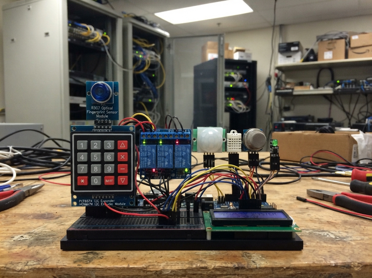
This server room security system demonstrates multi-layer access control and environmental monitoring using an Arduino Uno. The system combines fingerprint authentication with a numeric keypad, motion detection, temperature monitoring, and hazard sensors (smoke and flame) to protect a miniature server room model. Intruders trigger motion alarms, while authorized users can unlock doors and windows via relay control.
The guide provides a complete wiring diagram, parts list, and step-by-step assembly instructions for building the miniature room and connecting all sensors and outputs. The included firmware handles fingerprint matching, keypad entry, relay activation, environmental alerts, and real-time status display on an LCD screen, giving makers a foundation for understanding integrated security systems.
Wiring diagram

Gather all the parts
Assemble it in 7 steps
1. Prepare the miniature room
Build a small cardboard, foam-board, or acrylic room with a model door and window. Make two simple sliding latch bars from light plastic or cardboard so each 5 V miniature solenoid can pull one bar back by its short 3 mm movement.
- Test that each latch bar slides freely by hand before attaching a solenoid.
- These small solenoids are demonstration parts; keep the door and window light.
- Do not use these miniature latches on a real door, window, cabinet containing valuables, or an emergency exit.
2. Mount the small outputs
Glue or screw the 5 V fan near the top of the miniature room. Mount the door and window solenoids so each moving pin pulls its latch bar only when it receives a short pulse.
- Leave a little slack in the wires so opening the model door does not pull on the solenoid.
- The fan must be able to spin without touching cardboard or loose wires.
- The solenoids are intermittent-duty parts: holding them on can make them hot and damage them.
3. Wire the Arduino sensors
With the Uno unplugged, connect every sensor and display exactly as shown in the wiring diagram. The fingerprint sensor TX goes to D2 and RX goes to D3; the LCD and keypad expander share A4/SDA and A5/SCL.
- Keep the MQ-2 sensor outside or at the roof of the model because it is physically large and warms up.
- Make sure all sensor GND wires meet Arduino GND so every signal has the same reference.
- Do not swap 5 V and GND on the LCD or fingerprint sensor — swapped power can damage them.
4. Wire the lights and buzzer
Connect D11 through the red 220 ohm resistor to the red LED long leg, then connect its short leg to GND. Connect D12 through the green 220 ohm resistor to the green LED long leg, then connect its short leg to GND. Connect the buzzer signal to D10 and its GND pin to Arduino GND.
- The LED long leg is positive; the short leg is negative.
- The resistors protect the LEDs from receiving too much current.
- Never connect an LED directly between an Arduino pin and GND without its 220 ohm resistor; it can damage the LED or the Arduino pin.
5. Connect the relay control side
Connect relay VCC to Arduino 5 V, relay GND to Arduino GND, IN1 to D4, IN2 to D5, and IN3 to D6. Use a 3-channel relay board marked for 5 V Arduino inputs.
- The relay clicks when switched; that sound is normal.
- Keep relay screw terminals away from loose sensor jumper wires.
- Do not power the fan or solenoids from Arduino 5 V. Their current can overload the board.
6. Connect the separate 5 V miniature-load supply
Keep the Uno unplugged while wiring the load supply. Connect the adapter +5V to relay COM1, COM2, and COM3. Connect NO1 to the model door solenoid +5V, NO2 to the model window solenoid +5V, and NO3 to the fan +5V. Join the negative wires of both solenoids and the fan back to the adapter GND.
- Use the relay terminals marked COM and NO, not NC: the miniature latches should receive power only for a brief release pulse.
- A 5 V, 3 A regulated adapter provides enough margin for the two 1 A miniature latches and fan.
- Do not connect the separate adapter +5 V to Arduino 5 V; it is for relay contacts and the miniature loads only.
- Check the adapter label says 5 V DC before plugging it in — a higher-voltage adapter can damage the fan and latches.
7. Power and test the model
First plug the Uno into USB, then plug in the separate 5 V adapter. Test the green light, enter the keypad code, and test a registered fingerprint; either should give the door latch a short pull. Warm the DHT22 gently to test the fan, and use the sensor modules only as a classroom demonstration of alarm behavior.
- The default keypad code is 1234; change it in the firmware before presenting the model.
- The MQ-2 needs a warm-up period before its number becomes stable.
- Do not use flame, smoke, or a heat source near the cardboard model. These modules are for a low-risk demonstration, not real fire testing.
Review all connections
1. Connections between "fingerprint_1" and "Arduino"
2. Connections between "keypad_expander_1" and "Arduino"
3. Connections between "relay_1" and "Arduino"
4. Connections between "pir_1" and "Arduino"
5. Connections between "dht22_1" and "Arduino"
6. Connections between "mq2_1" and "Arduino"
7. Connections between "flame_1" and "Arduino"
8. Connections between "lcd_1" and "Arduino"
9. Connections between "buzzer_1" and "Arduino"
10. Connections between "red_resistor_1" and "Arduino"
11. Connections between "red_led_1" and "Arduino"
12. Connections between "green_resistor_1" and "Arduino"
13. Connections between "green_led_1" and "Arduino"
14. Connections between "supply_12v_1" and "Arduino"
15. Connections between "door_lock_1" and "Arduino"
16. Connections between "window_lock_1" and "Arduino"
Deploy the firmware
#include <Arduino.h>
#include <Wire.h>
#include <Adafruit_Fingerprint.h>
#include <DHT.h>
#include <LiquidCrystal_I2C.h>


// Forward declarations
void setTransient(const String &message, unsigned long durationMs);
void pulseDoorLatch();
void pulseWindowLatch();
void updateLatches();
void pollKeypad();
bool fingerprintMatched();
void showStatus(float temperature, float humidity, int smoke, bool emergency, bool intrusion);

const uint8_t FINGERPRINT_RX_PIN = 0;
const uint8_t FINGERPRINT_TX_PIN = 1;
const uint8_t DOOR_RELAY_PIN = 4;
const uint8_t WINDOW_RELAY_PIN = 5;
const uint8_t FAN_RELAY_PIN = 6;
const uint8_t PIR_PIN = 7;
const uint8_t DHT_PIN = 8;
const uint8_t FLAME_DIGITAL_PIN = 9;
const uint8_t BUZZER_PIN = 10;
const uint8_t RED_LED_PIN = 11;
const uint8_t GREEN_LED_PIN = 12;
const uint8_t MQ2_PIN = A0;
const uint8_t FLAME_ANALOG_PIN = A1;

const uint8_t KEYPAD_ADDRESS = 0x20;
const uint8_t LCD_ADDRESS = 0x27;
const char ACCESS_CODE[] = "1234"; // Change this before displaying the model.
const int SMOKE_THRESHOLD = 450;
const float FAN_ON_C = 30.0;
const float FAN_OFF_C = 28.0;
const unsigned long LATCH_PULSE_MS = 800;
const unsigned long DISPLAY_PERIOD_MS = 1000;

// Most small relay boards are active-low.
const uint8_t RELAY_ON = LOW;
const uint8_t RELAY_OFF = HIGH;

// Use the Uno hardware UART for the R307. This avoids the ESP-only serial
// implementation that is incompatible with the browser simulator.
Adafruit_Fingerprint finger(&Serial);
DHT dht(DHT_PIN, DHT22);
LiquidCrystal_I2C lcd(LCD_ADDRESS, 16, 2);

const char keyMap[4][4] = {{'1','2','3','A'}, {'4','5','6','B'}, {'7','8','9','C'}, {'*','0','#','D'}};
char enteredCode[5] = "";
uint8_t enteredLength = 0;
bool armed = true;
bool fanOn = false;
bool releasedForThisAlarm = false;
unsigned long doorPulseUntil = 0;
unsigned long windowPulseUntil = 0;
unsigned long lastDisplay = 0;
String transientMessage = "Starting...";
unsigned long transientUntil = 0;

void setTransient(const String &message, unsigned long durationMs) {
  transientMessage = message;
  transientUntil = millis() + durationMs;
}

void pulseDoorLatch() {
  doorPulseUntil = millis() + LATCH_PULSE_MS;
  setTransient("Door unlocked", 1500);
}

void pulseWindowLatch() {
  windowPulseUntil = millis() + LATCH_PULSE_MS;
}

void updateLatches() {
  // These miniature 5 V latches are intermittent-duty parts: pulse them briefly only.
  digitalWrite(DOOR_RELAY_PIN, millis() < doorPulseUntil ? RELAY_ON : RELAY_OFF);
  digitalWrite(WINDOW_RELAY_PIN, millis() < windowPulseUntil ? RELAY_ON : RELAY_OFF);
}

void pollKeypad() {
  for (uint8_t row = 0; row < 4; row++) {
    uint8_t pattern = 0xFF;
    bitClear(pattern, row);
    Wire.beginTransmission(KEYPAD_ADDRESS); Wire.write(pattern); Wire.endTransmission();
    delayMicroseconds(80);
    Wire.requestFrom(KEYPAD_ADDRESS, (uint8_t)1);
    if (!Wire.available()) continue;
    uint8_t reading = Wire.read();
    for (uint8_t col = 0; col < 4; col++) {
      if (!bitRead(reading, col + 4)) {
        char key = keyMap[row][col];
        while (true) {
          Wire.beginTransmission(KEYPAD_ADDRESS); Wire.write(pattern); Wire.endTransmission();
          Wire.requestFrom(KEYPAD_ADDRESS, (uint8_t)1);
          if (!Wire.available() || bitRead(Wire.read(), col + 4)) break;
          delay(10);
        }
        Wire.beginTransmission(KEYPAD_ADDRESS); Wire.write(0xFF); Wire.endTransmission();
        if (key == '*') {
          enteredLength = 0; enteredCode[0] = '\0'; setTransient("Code cleared", 1000);
        } else if (key == '#') {
          if (strcmp(enteredCode, ACCESS_CODE) == 0) pulseDoorLatch();
          else setTransient("Access denied", 2000);
          enteredLength = 0; enteredCode[0] = '\0';
        } else if (key == 'A') {
          armed = !armed; setTransient(armed ? "System armed" : "System disarmed", 1500);
        } else if (key >= '0' && key <= '9' && enteredLength < 4) {
          enteredCode[enteredLength++] = key; enteredCode[enteredLength] = '\0';
          setTransient("Code: " + String(enteredLength) + " digits", 700);
        }
        return;
      }
    }
  }
  Wire.beginTransmission(KEYPAD_ADDRESS); Wire.write(0xFF); Wire.endTransmission();
}

bool fingerprintMatched() {
  if (finger.getImage() != FINGERPRINT_OK) return false;
  if (finger.image2Tz() != FINGERPRINT_OK) { setTransient("Print not read", 1500); return false; }
  if (finger.fingerFastSearch() == FINGERPRINT_OK) { setTransient("Fingerprint OK", 1500); return true; }
  setTransient("Print denied", 1500);
  return false;
}

void showStatus(float temperature, float humidity, int smoke, bool emergency, bool intrusion) {
  if (millis() - lastDisplay < DISPLAY_PERIOD_MS && millis() > transientUntil) return;
  lastDisplay = millis();
  lcd.setCursor(0, 0);
  String upper;
  if (emergency) upper = "FIRE/SMOKE ALERT";
  else if (intrusion) upper = "INTRUSION ALERT ";
  else if (millis() < transientUntil) upper = transientMessage;
  else upper = "T:" + String(temperature, 1) + "C H:" + String(humidity, 0) + "%";
  upper += "                ";
  lcd.print(upper.substring(0, 16));
  lcd.setCursor(0, 1);
  String lower = "S:" + String(smoke) + (armed ? " ARMED" : " DISARMED") + "       ";
  lcd.print(lower.substring(0, 16));
}

void setup() {
  pinMode(DOOR_RELAY_PIN, OUTPUT); pinMode(WINDOW_RELAY_PIN, OUTPUT); pinMode(FAN_RELAY_PIN, OUTPUT);
  pinMode(PIR_PIN, INPUT); pinMode(FLAME_DIGITAL_PIN, INPUT);
  pinMode(BUZZER_PIN, OUTPUT); pinMode(RED_LED_PIN, OUTPUT); pinMode(GREEN_LED_PIN, OUTPUT);
  digitalWrite(DOOR_RELAY_PIN, RELAY_OFF); digitalWrite(WINDOW_RELAY_PIN, RELAY_OFF);
  digitalWrite(FAN_RELAY_PIN, RELAY_OFF); digitalWrite(BUZZER_PIN, LOW);
  digitalWrite(RED_LED_PIN, LOW); digitalWrite(GREEN_LED_PIN, HIGH);
  Wire.begin();
  lcd.init(); lcd.backlight(); lcd.clear(); lcd.print("Mini server room"); lcd.setCursor(0, 1); lcd.print("Starting sensors");
  dht.begin();
  Serial.begin(57600); finger.begin(57600); delay(300);
  if (!finger.verifyPassword()) setTransient("Finger sensor err", 3000);
  Wire.beginTransmission(KEYPAD_ADDRESS); Wire.write(0xFF); Wire.endTransmission();
}

void loop() {
  pollKeypad();
  float humidity = dht.readHumidity();
  float temperature = dht.readTemperature();
  if (isnan(humidity)) humidity = 0;
  if (isnan(temperature)) temperature = 0;
  int smoke = analogRead(MQ2_PIN);
  bool flame = digitalRead(FLAME_DIGITAL_PIN) == LOW;
  bool emergency = flame || smoke >= SMOKE_THRESHOLD || temperature >= 55.0;
  bool intrusion = armed && digitalRead(PIR_PIN) == HIGH && !emergency;

  if (temperature >= FAN_ON_C) fanOn = true;
  if (temperature <= FAN_OFF_C) fanOn = false;
  digitalWrite(FAN_RELAY_PIN, fanOn ? RELAY_ON : RELAY_OFF);

  if (emergency) {
    // Model-only response: momentarily open both small latches once per alarm event.
    if (!releasedForThisAlarm) { pulseDoorLatch(); pulseWindowLatch(); releasedForThisAlarm = true; }
    digitalWrite(RED_LED_PIN, HIGH); digitalWrite(GREEN_LED_PIN, LOW); tone(BUZZER_PIN, 1800);
  } else {
    releasedForThisAlarm = false;
    digitalWrite(RED_LED_PIN, intrusion ? HIGH : LOW); digitalWrite(GREEN_LED_PIN, intrusion ? LOW : HIGH);
    if (intrusion) tone(BUZZER_PIN, 1200); else noTone(BUZZER_PIN);
    if (millis() >= doorPulseUntil && fingerprintMatched()) pulseDoorLatch();
  }
  updateLatches();
  showStatus(temperature, humidity, smoke, emergency, intrusion);
  delay(50);
}
Remix this project
Make it yours in one click
Open a full copy of this project in your own Schematik workspace — diagram, code, parts, and assembly steps included. Swap the sensor, add features, or redesign the whole thing with AI. The author's original stays untouched.