Community project
Two-Way Traffic Control
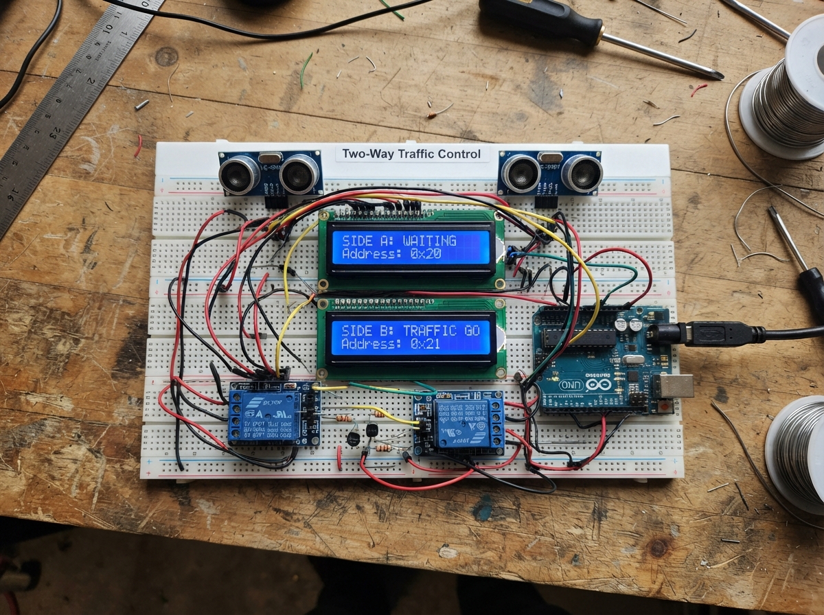
This project implements an automated two-way traffic control system using ultrasonic sensors to detect vehicles approaching from either direction. An Arduino Uno coordinates two independent traffic lanes, each with its own relay-controlled indicator lights and I2C LCD display showing real-time status and countdown timers.
The guide provides a complete wiring diagram, parts list, and step-by-step assembly instructions for building the dual relay drivers, connecting the HC-SR04 distance sensors, and mounting the indicator lamps. You'll also get the full Arduino firmware that manages traffic state transitions, vehicle detection logic, and synchronized display updates across both lanes.
Wiring diagram

Gather all the parts
Assemble it in 7 steps
1. Keep the two power supplies separate
Leave the 12 V bulb adapter unplugged while you wire. Power the Arduino later through its USB socket. Connect the 12 V adapter's GND terminal to an Arduino GND pin with one jumper so the relay-driver transistors have the same zero-volt reference.
- Do not connect the 12 V positive wire to any Arduino pin or Arduino 5 V pin — that can permanently damage the board. Use only 12 V low-voltage lamps, never household mains bulbs.
2. Wire both distance sensors
For sensor_a, connect VCC to Arduino 5V (power), GND to Arduino GND (ground), TRIG to D2 (signal), and ECHO to D3 (signal). For sensor_b, connect VCC to 5V (power), GND to GND (ground), TRIG to D4 (signal), and ECHO to D5 (signal). Point each sensor toward its own vehicle approach.
- The two round metal circles on each sensor must face the object being detected.
3. Wire the two LCD screens
On both lcd_a and lcd_b, connect VCC to Arduino 5V (power), GND to Arduino GND (ground), SDA to A4 (data), and SCL to A5 (clock). These two LCDs share the same A4 and A5 wires; their different addresses, 0x20 and 0x21, let the Arduino talk to each screen separately.
- Make sure VCC and GND are not swapped — swapped power can damage an LCD module.
4. Build Side A's relay driver
Place driver_a in the breadboard and first check its specific 2N2222 or BC547 pin order from its marking or data sheet, because similar-looking transistors can have different leg orders. Connect its emitter to Arduino GND (ground). Connect one end of base_resistor_a to D8 (signal), then connect its other end to the transistor base (signal). Connect the transistor collector to relay_a COIL-. Connect relay_a COIL+ to Arduino 5V (power). Place diode_a across the relay coil: its striped cathode end goes to COIL+ and its unstriped anode end goes to COIL-.
- The diode stripe must face the relay coil's 5 V side; reversing it makes a short circuit when the relay turns on.
- Do not connect a relay coil directly to D8 — the transistor and 1 kΩ resistor protect the Arduino.
5. Build Side B's relay driver
Repeat the same wiring for Side B. Connect driver_b's emitter to Arduino GND (ground). Connect D9 to one end of base_resistor_b (signal), its other end to driver_b's base (signal), and driver_b's collector to relay_b COIL-. Connect relay_b COIL+ to Arduino 5V (power). Place diode_b across the relay coil with its striped cathode end on COIL+ and its unstriped anode end on COIL-.
- The relay coil wiring is separate from its COM, NC, and NO lamp-contact terminals; do not mix those terminals up.
6. Wire the low-voltage lamps through the relay contacts
With the 12 V adapter still unplugged, connect bulb_supply +12V to relay_a COM (lamp power), then jumper relay_a COM to relay_b COM (lamp power). Connect relay_a NC to bulb_a_red + (red-lamp power) and relay_a NO to bulb_a_green + (green-lamp power). Connect relay_b NC to bulb_b_red + (red-lamp power) and relay_b NO to bulb_b_green + (green-lamp power). Connect every bulb negative terminal to bulb_supply GND (ground).
- NC means the red lamp is powered whenever that relay is off; NO means the green lamp is powered only when that relay is on.
- Confirm every lamp is rated for the adapter voltage, 12 V. Never substitute mains-powered lamps or expose bare high-voltage wiring.
7. Power and check the starting condition
Plug the Arduino into USB first. Both relay coils should be off, so both red lamps should be on after you plug in the 12 V bulb adapter. Each LCD should show its side as RED. Put an object closer than 30 cm in front of one sensor to begin that side's five-second PENDING display.
- If an LCD stays blank, adjust its small contrast screw slowly with a screwdriver after checking its power wires.
Review all connections
1. Connections between "sensor_a" and "Arduino"
2. Connections between "sensor_b" and "Arduino"
3. Connections between "lcd_a" and "Arduino"
4. Connections between "lcd_b" and "Arduino"
5. Connections between "base_resistor_a" and "Arduino"
6. Connections between "driver_a" and "Arduino"
7. Connections between "relay_a" and "Arduino"
8. Connections between "diode_a" and "Arduino"
9. Connections between "base_resistor_b" and "Arduino"
10. Connections between "driver_b" and "Arduino"
11. Connections between "relay_b" and "Arduino"
12. Connections between "diode_b" and "Arduino"
13. Connections between "bulb_supply" and "Arduino"
14. Connections between "bulb_a_red" and "Arduino"
15. Connections between "bulb_a_green" and "Arduino"
16. Connections between "bulb_b_red" and "Arduino"
17. Connections between "bulb_b_green" and "Arduino"
Deploy the firmware
#include <Arduino.h>
#include <Wire.h>
#include <NewPing.h>
#include <LiquidCrystal_I2C.h>


// Hoisted type definitions
enum TrafficState { IDLE, PENDING_A, PENDING_B, CONFIRM_A, CONFIRM_B, GREEN_A, GREEN_B };


// Forward declarations
bool vehicleDetected(NewPing &sonar);
bool sideAIsGreen();
bool sideBIsGreen();
void setLights();
long secondsForSide(bool isA, unsigned long now);
void writeLine(LiquidCrystal_I2C &lcd, byte row, const char *text);
void drawDisplays(unsigned long now, bool force);
void enterState(TrafficState next, unsigned long now);

const byte TRIG_A_PIN = 2;
const byte ECHO_A_PIN = 3;
const byte TRIG_B_PIN = 4;
const byte ECHO_B_PIN = 5;
const byte RELAY_A_PIN = 8;
const byte RELAY_B_PIN = 9;

const unsigned int DETECTION_CM = 30;
const unsigned int MAX_DISTANCE_CM = 200;
const unsigned long PENDING_MS = 5000UL;
const unsigned long GREEN_MS = 50000UL;
const unsigned long CONFIRM_MS = 3000UL;
const unsigned long SENSOR_INTERVAL_MS = 100UL;

NewPing sonarA(TRIG_A_PIN, ECHO_A_PIN, MAX_DISTANCE_CM);
NewPing sonarB(TRIG_B_PIN, ECHO_B_PIN, MAX_DISTANCE_CM);
LiquidCrystal_I2C lcdA(0x20, 16, 2);
LiquidCrystal_I2C lcdB(0x21, 16, 2);


TrafficState state = IDLE;
unsigned long stateStartedAt = 0;
unsigned long lastSensorAt = 0;
bool vehicleA = false;
bool vehicleB = false;
TrafficState lastDrawnState = IDLE;
long lastDrawnSeconds = -1;

bool vehicleDetected(NewPing &sonar) {
  unsigned int distance = sonar.ping_cm();
  return distance > 0 && distance < DETECTION_CM;
}

bool sideAIsGreen() {
  return state == GREEN_A;
}

bool sideBIsGreen() {
  return state == GREEN_B;
}

void setLights() {
  // HIGH energizes a relay. The SPDT relay then moves from red (NC) to green (NO).
  // The two conditions are mutually exclusive by construction.
  digitalWrite(RELAY_A_PIN, sideAIsGreen() ? HIGH : LOW);
  digitalWrite(RELAY_B_PIN, sideBIsGreen() ? HIGH : LOW);
}

const char *stateWordA() {
  if (state == PENDING_A || state == CONFIRM_A) return "PENDING";
  if (state == GREEN_A) return "GO";
  return "RED";
}

const char *stateWordB() {
  if (state == PENDING_B || state == CONFIRM_B) return "PENDING";
  if (state == GREEN_B) return "GO";
  return "RED";
}

long secondsForSide(bool isA, unsigned long now) {
  bool timed = (isA && (state == PENDING_A || state == CONFIRM_A || state == GREEN_A)) ||
               (!isA && (state == PENDING_B || state == CONFIRM_B || state == GREEN_B));
  if (!timed) return -1;

  unsigned long duration = (state == GREEN_A || state == GREEN_B) ? GREEN_MS :
                           (state == CONFIRM_A || state == CONFIRM_B) ? CONFIRM_MS : PENDING_MS;
  unsigned long elapsed = now - stateStartedAt;
  if (elapsed >= duration) return 0;
  return (long)((duration - elapsed + 999UL) / 1000UL);
}

void writeLine(LiquidCrystal_I2C &lcd, byte row, const char *text) {
  char padded[17];
  snprintf(padded, sizeof(padded), "%-16s", text);
  lcd.setCursor(0, row);
  lcd.print(padded);
}

void drawDisplays(unsigned long now, bool force) {
  long seconds = (state == PENDING_A || state == CONFIRM_A || state == GREEN_A) ? secondsForSide(true, now) :
                 (state == PENDING_B || state == CONFIRM_B || state == GREEN_B) ? secondsForSide(false, now) : -1;
  if (!force && state == lastDrawnState && seconds == lastDrawnSeconds) return;

  char line[17];
  snprintf(line, sizeof(line), "Side A %-9s", stateWordA());
  writeLine(lcdA, 0, line);
  if (secondsForSide(true, now) < 0) snprintf(line, sizeof(line), "Time -- B:%-7s", stateWordB());
  else snprintf(line, sizeof(line), "Time %2lds B:%-5s", secondsForSide(true, now), stateWordB());
  writeLine(lcdA, 1, line);

  snprintf(line, sizeof(line), "Side B %-9s", stateWordB());
  writeLine(lcdB, 0, line);
  if (secondsForSide(false, now) < 0) snprintf(line, sizeof(line), "Time -- A:%-7s", stateWordA());
  else snprintf(line, sizeof(line), "Time %2lds A:%-5s", secondsForSide(false, now), stateWordA());
  writeLine(lcdB, 1, line);

  lastDrawnState = state;
  lastDrawnSeconds = seconds;
}

void enterState(TrafficState next, unsigned long now) {
  state = next;
  stateStartedAt = now;
  setLights();
  drawDisplays(now, true);
}

void setup() {
  pinMode(RELAY_A_PIN, OUTPUT);
  pinMode(RELAY_B_PIN, OUTPUT);
  digitalWrite(RELAY_A_PIN, LOW);
  digitalWrite(RELAY_B_PIN, LOW);

  Wire.begin();
  lcdA.init();
  lcdA.backlight();
  lcdB.init();
  lcdB.backlight();

  unsigned long now = millis();
  enterState(IDLE, now);
}

void loop() {
  unsigned long now = millis();

  if (now - lastSensorAt >= SENSOR_INTERVAL_MS) {
    lastSensorAt = now;
    vehicleA = vehicleDetected(sonarA);
    vehicleB = vehicleDetected(sonarB);
  }

  switch (state) {
    case IDLE:
      if (vehicleA) enterState(PENDING_A, now);
      else if (vehicleB) enterState(PENDING_B, now);
      break;

    case PENDING_A:
      if (now - stateStartedAt >= PENDING_MS) enterState(CONFIRM_A, now);
      break;
    case PENDING_B:
      if (now - stateStartedAt >= PENDING_MS) enterState(CONFIRM_B, now);
      break;

    // A fresh reading inside the next three seconds confirms that a vehicle is still waiting.
    case CONFIRM_A:
      if (vehicleA) enterState(GREEN_A, now);
      else if (now - stateStartedAt >= CONFIRM_MS) enterState(IDLE, now);
      break;
    case CONFIRM_B:
      if (vehicleB) enterState(GREEN_B, now);
      else if (now - stateStartedAt >= CONFIRM_MS) enterState(IDLE, now);
      break;

    case GREEN_A:
      if (now - stateStartedAt >= GREEN_MS) enterState(PENDING_B, now);
      break;
    case GREEN_B:
      if (now - stateStartedAt >= GREEN_MS) enterState(PENDING_A, now);
      break;
  }

  drawDisplays(now, false);
}
Remix this project
Make it yours in one click
Open a full copy of this project in your own Schematik workspace — diagram, code, parts, and assembly steps included. Swap the sensor, add features, or redesign the whole thing with AI. The author's original stays untouched.
Related projects
Bueno Entonces Creamos El Control Tmb O Lo
Arduino · September 30, 2026nicolas onguino
Server Room Security System
Arduino · September 30, 2026Mark Christian S. Maraviles
Interactive Water Well
Arduino · September 29, 2026Sof Salamanca