Community project
ToF Distance Monitor
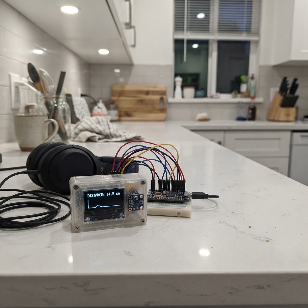
This project uses a VL53L0X Time-of-Flight sensor connected to an Arduino Uno to measure distances up to 1.2 meters with high accuracy. The sensor works by emitting infrared light and measuring the time it takes to reflect back, making it ideal for proximity detection, object tracking, and distance monitoring applications.
The guide includes a complete wiring diagram showing I2C connections, a full parts list, and ready-to-upload firmware that displays distance measurements in millimeters via the serial monitor. Assembly takes just minutes—connect power, ground, and the two I2C signal wires, then upload the code to start reading distances.
Wiring diagram

Gather all the parts
Assemble it in 4 steps
1. Disconnect USB power
Unplug the Arduino Uno USB cable before making any connections.
- Do not connect or move wires while the board is powered.
2. Connect power and ground
Connect the VL53L0X VIN pin to the Uno 5V pin. Connect the VL53L0X GND pin to an Uno GND pin.
- Use the pins labelled VIN and GND on the breakout; do not use the sensor's XSHUT or GPIO1 pins for this project.
- This design assumes the common breakout module whose VIN input accepts 5 V. If your board is labelled 3V3-only rather than VIN, power it from the Uno 3.3V pin instead.
3. Connect the I2C signal wires
Connect VL53L0X SDA to Uno A4, and VL53L0X SCL to Uno A5. The Uno’s A4/A5 pins also serve as the I2C data and clock connections.
- Keep the four sensor wires short and secure for reliable I2C communication.
- Do not swap SDA and SCL.
4. Power the board and view readings
Reconnect USB power. Use Schematik’s Deploy button to compile and flash the project, then open its serial monitor at 115200 baud to view distance readings in millimetres about four times per second.
- Aim the sensor toward a nearby non-transparent object for an initial test.
- Avoid staring into the sensor aperture at close range.
Review all connections
1. Connections between "vl53l0x_1" and "Arduino"
Deploy the firmware
#include <Arduino.h>
#include <Wire.h>
#include <Adafruit_VL53L0X.h>

Adafruit_VL53L0X lox;

const unsigned long MEASUREMENT_INTERVAL_MS = 250;
unsigned long lastMeasurementMs = 0;

void setup() {
  Serial.begin(115200);
  Wire.begin();

  Serial.println(F("VL53L0X distance sensor starting..."));
  if (!lox.begin()) {
    Serial.println(F("VL53L0X not found. Check VIN, GND, SDA, and SCL wiring."));
    while (true) {
      delay(1000);
    }
  }

  Serial.println(F("VL53L0X ready. Distance is printed in millimetres."));
}

void loop() {
  if (millis() - lastMeasurementMs < MEASUREMENT_INTERVAL_MS) {
    return;
  }
  lastMeasurementMs = millis();

  VL53L0X_RangingMeasurementData_t measurement;
  lox.rangingTest(&measurement, false);

  if (measurement.RangeStatus != 4) {
    Serial.print(F("Distance: "));
    Serial.print(measurement.RangeMilliMeter);
    Serial.println(F(" mm"));
  } else {
    Serial.println(F("Distance: out of range"));
  }
}
Remix this project
Make it yours in one click
Open a full copy of this project in your own Schematik workspace — diagram, code, parts, and assembly steps included. Swap the sensor, add features, or redesign the whole thing with AI. The author's original stays untouched.