Community project
Tsunami Warning Detector
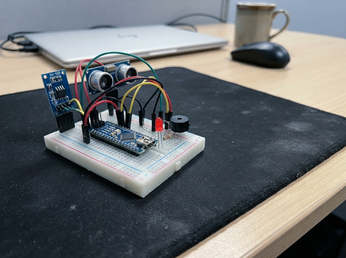
This tsunami warning detector uses an ESP32 microcontroller to monitor for both seismic activity and rapid water-level changes. The SW-420 vibration sensor detects ground shaking, while an HC-SR04 ultrasonic sensor tracks water distance in real time, triggering an audible alarm and visual indicator when dangerous conditions are detected.
This guide provides a complete wiring diagram, parts list, and step-by-step assembly instructions to build your own early warning system. The included firmware continuously samples vibration and water levels, comparing measurements against baseline thresholds to identify potential threats and activate alerts automatically.
Wiring diagram

Gather all the parts
Assemble it in 6 steps
1. Place and power the ESP32
Place the ESP32 across the breadboard center gap. Use the ESP32 3V3 pin for the 3.3 V rail and GND for the ground rail. Use the ESP32 5V/VIN pin only for the HC-SR04 5 V supply rail. Power the finished project from the ESP32 USB connector.
- Keep all ground rails connected together.
- Do not connect the 5 V rail to any ESP32 GPIO.
- Disconnect USB power before moving wires.
2. Wire the SW-420 vibration detector
Connect SW-420 VCC to the 3.3 V rail, GND to ground, and DO to ESP32 GPIO32. Turn the module trimmer gently to set the desired vibration sensitivity.
- The yellow LED turns on when the module’s digital output is LOW, which is the common SW-420 active state.
- Power the SW-420 from 3.3 V, not 5 V, so its DO signal stays safe for the 3.3 V ESP32 input.
3. Add the yellow vibration LED
Connect ESP32 GPIO25 to one end of the 220 Ω resistor. Connect the other resistor end to the yellow LED long lead (anode). Connect the LED short lead (cathode/flat-side lead) to ground.
- The resistor may be placed on either side of the LED, but it must remain in series with it.
- Never connect an LED directly from a GPIO to ground without its series resistor.
4. Wire the ultrasonic water-level sensor safely
Mount the HC-SR04 above the water surface with its transducers facing down. Connect VCC to 5 V, GND to common ground, and TRIG to GPIO27. For ECHO, connect HC-SR04 ECHO to the 1 kΩ resistor, connect the resistor’s other end to GPIO33, then connect the 2 kΩ resistor from that same GPIO33 divider junction to ground.
- The 1 kΩ and 2 kΩ resistors make a divider that reduces the HC-SR04’s 5 V ECHO pulse to about 3.3 V.
- Keep the sensor dry and positioned so it has a clear view of the water surface.
- Never wire the HC-SR04 ECHO pin directly to GPIO33: it outputs 5 V and can damage the ESP32.
- The ordinary HC-SR04 board is not waterproof; keep electronics away from splash and condensation.
5. Connect the audible alarm
Connect buzzer SIGNAL/+ to GPIO26 and buzzer GND/− to the common ground rail.
- If your buzzer is marked + and −, GPIO26 goes to + and ground goes to −.
- Use a small piezo or low-current buzzer. A larger high-current buzzer needs a transistor driver, which is not part of this build.
6. Check before powering
Check that every module shares ground, the HC-SR04 alone is powered from 5 V, the SW-420 is powered from 3.3 V, and the HC-SR04 ECHO divider is installed. After deploying, let the sensor take its initial distance reading with normal water level present.
- A rising water level makes the measured distance decrease; a falling level makes it increase. Either direction triggers when the change between readings reaches 3 cm.
- This prototype is an educational local alarm, not a certified tsunami-warning instrument. Do not rely on it for public safety decisions.
Review all connections
1. Connections between "vibration_sensor" and "ESP32"
2. Connections between "water_sensor" and "ESP32"
3. Connections between "echo_bottom_resistor" and "ESP32"
4. Connections between "led_resistor" and "ESP32"
5. Connections between "vibration_led" and "ESP32"
6. Connections between "alarm_buzzer" and "ESP32"
7. Connections between "echo_top_resistor" and "ESP32"
Deploy the firmware
#include <Arduino.h>


// Forward declarations
float measureDistanceCm();
void startAlarm();
void stopAlarm();

constexpr int VIBRATION_PIN = 32;
constexpr int TRIG_PIN = 27;
constexpr int ECHO_PIN = 33;
constexpr int YELLOW_LED_PIN = 25;
constexpr int BUZZER_PIN = 26;

constexpr float CHANGE_THRESHOLD_CM = 3.0f;
constexpr unsigned long SAMPLE_INTERVAL_MS = 250;
constexpr unsigned long ALARM_DURATION_MS = 10000;
constexpr unsigned long ECHO_TIMEOUT_US = 30000;

float baselineDistanceCm = NAN;
unsigned long lastSampleMs = 0;
unsigned long alarmStartedMs = 0;
bool alarmActive = false;

float measureDistanceCm() {
  digitalWrite(TRIG_PIN, LOW);
  delayMicroseconds(2);
  digitalWrite(TRIG_PIN, HIGH);
  delayMicroseconds(10);
  digitalWrite(TRIG_PIN, LOW);

  const unsigned long durationUs = pulseIn(ECHO_PIN, HIGH, ECHO_TIMEOUT_US);
  if (durationUs == 0) {
    return NAN;
  }
  return (durationUs * 0.0343f) / 2.0f;
}

void startAlarm() {
  if (!alarmActive) {
    alarmActive = true;
    alarmStartedMs = millis();
    ledcWriteTone(BUZZER_PIN, 2200);
  }
}

void stopAlarm() {
  ledcWriteTone(BUZZER_PIN, 0);
  alarmActive = false;
}

void setup() {
  Serial.begin(115200);

  pinMode(VIBRATION_PIN, INPUT);
  pinMode(TRIG_PIN, OUTPUT);
  pinMode(ECHO_PIN, INPUT);
  pinMode(YELLOW_LED_PIN, OUTPUT);
  digitalWrite(YELLOW_LED_PIN, LOW);

  ledcAttach(BUZZER_PIN, 2200, 8);
  stopAlarm();

  delay(500);
  baselineDistanceCm = measureDistanceCm();
  Serial.println("Tsunami detector started.");
  if (isnan(baselineDistanceCm)) {
    Serial.println("Waiting for a valid ultrasonic reading...");
  } else {
    Serial.printf("Initial water distance: %.1f cm\n", baselineDistanceCm);
  }
}

void loop() {
  // SW-420 modules commonly assert LOW when vibration is detected.
  const bool vibrationDetected = digitalRead(VIBRATION_PIN) == LOW;
  digitalWrite(YELLOW_LED_PIN, vibrationDetected ? HIGH : LOW);

  const unsigned long now = millis();
  if (now - lastSampleMs >= SAMPLE_INTERVAL_MS) {
    lastSampleMs = now;
    const float distanceCm = measureDistanceCm();

    if (!isnan(distanceCm)) {
      if (isnan(baselineDistanceCm)) {
        baselineDistanceCm = distanceCm;
        Serial.printf("Water baseline set: %.1f cm\n", baselineDistanceCm);
      } else {
        const float changeCm = fabsf(distanceCm - baselineDistanceCm);
        Serial.printf("Distance: %.1f cm, change: %.1f cm\n", distanceCm, changeCm);

        if (changeCm >= CHANGE_THRESHOLD_CM) {
          startAlarm();
        } else {
          // A stable water level ends the alarm immediately.
          stopAlarm();
        }
        baselineDistanceCm = distanceCm;
      }
    }
  }

  // Continue an active alarm for up to ten seconds if level changes persist.
  if (alarmActive && (now - alarmStartedMs >= ALARM_DURATION_MS)) {
    stopAlarm();
  }
}
Remix this project
Make it yours in one click
Open a full copy of this project in your own Schematik workspace — diagram, code, parts, and assembly steps included. Swap the sensor, add features, or redesign the whole thing with AI. The author's original stays untouched.