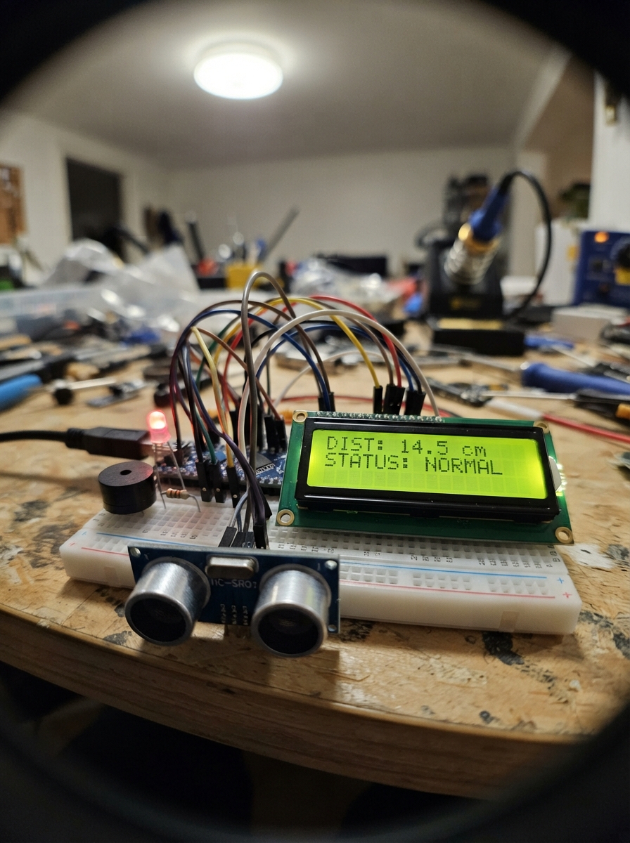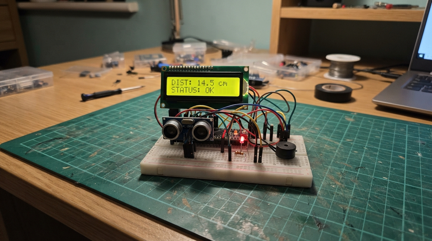
This project builds a real-time distance monitoring system using an ultrasonic sensor to detect how far objects are from the Arduino. The HC-SR04 sensor measures distance by sending sound waves and timing their return, while the system displays readings on a 20x4 LCD screen and provides visual and audio feedback through color-coded LEDs and a piezo buzzer that respond to different distance ranges.
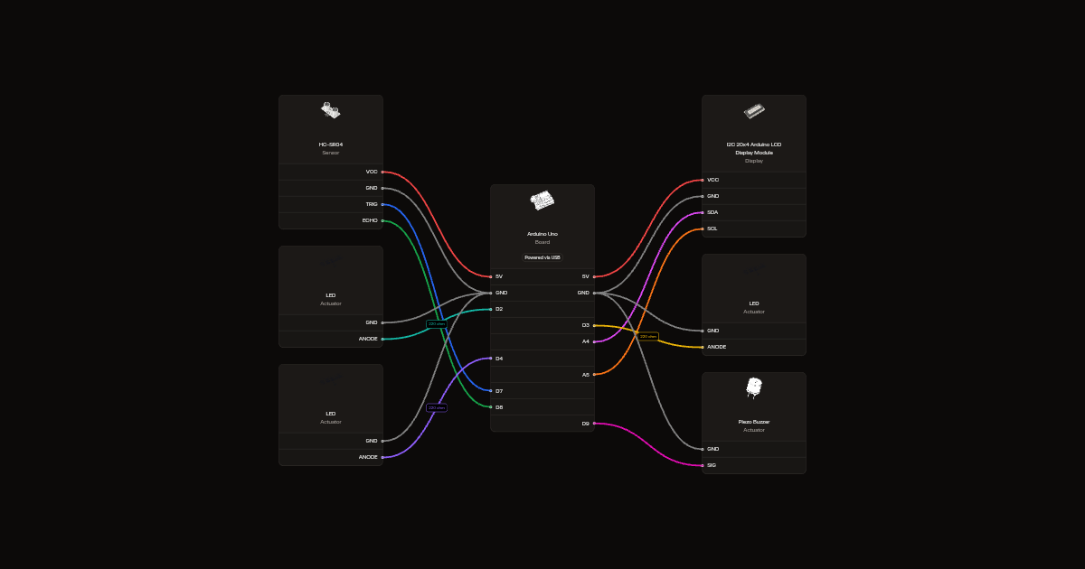
The guide includes a complete wiring diagram showing how to connect the ultrasonic sensor, LCD display, three LEDs with current-limiting resistors, and piezo buzzer to the Arduino Uno. You'll also get the full firmware code, a detailed parts list, and step-by-step assembly instructions that walk through sensor calibration, display initialization, and testing the distance detection thresholds.
Wiring diagram
Gather all the parts
Assemble it in 6 steps
1. Disconnect USB before wiring
Use jumper wires to make the connections shown in the circuit. Keep power disconnected until all wires are checked.
2. Connect the distance sensor
Connect VCC to 5V and GND to GND. Connect TRIG to D7 to start measurements and ECHO to D8 to receive the echo timing. Point the two round transducers toward the object.
3. Connect the four-row LCD
Connect VCC to 5V, GND to GND, SDA to A4 (data), and SCL to A5 (clock). Use the DFRobot DFR0154 20x4 I2C display with all three address jumpers connected for address 0x20. Read the printed pin labels rather than assuming connector order.
- Adjust the contrast control if the backlight lights but the text is invisible.
- This LCD has no listed simulator support; full LCD simulation is not verified.
4. Connect each LED through its resistor
Connect D2 through rred (220 ohm) to the red LED long leg. Connect D3 through ryellow to the yellow LED long leg. Connect D4 through rblue to the blue LED long leg. Connect every short leg (flat-edge side) to GND. Each resistor limits LED current.
5. Connect the passive piezo
Connect one piezo lead to D9 (alarm tone) and the other to GND. Use the listed passive piezo, not a high-current magnetic buzzer.
6. Check and test the physical circuit
Check all power connections before plugging in USB. After firmware deployment, move a flat object to 5, 12, 18 and 25 cm. Expect blue and alarm, yellow only, no LEDs, and red only respectively. Remove the target to test No Reading; distant surfaces may still return a valid echo. Serial output uses 9600 baud.
Review all connections
1. Connections between "sonar" and "Arduino"
2. Connections between "lcd" and "Arduino"
3. Connections between "rred" and "Arduino"
4. Connections between "red" and "Arduino"
5. Connections between "ryellow" and "Arduino"
6. Connections between "yellow" and "Arduino"
7. Connections between "rblue" and "Arduino"
8. Connections between "blue" and "Arduino"
9. Connections between "alarm" and "Arduino"
Deploy the firmware
#include <Arduino.h>
#include <Wire.h>
#include <LiquidCrystal_I2C.h>

// =====================================
// PIN CONFIGURATION
// =====================================

const int RED = 2;
const int YELLOW = 3;
const int BLUE = 4;

const int TRIG = 7;
const int ECHO = 8;
const int BUZZER = 9;

// =====================================
// LCD CONFIGURATION
// =====================================

// LCD address 0x20, 20 columns, 4 rows
LiquidCrystal_I2C lcd(0x20, 20, 4);

bool lcdReady = false;

// =====================================
// VARIABLES
// =====================================

unsigned long lastSample = 0;

int previousState = -1;

char previous[4][21] = {};

// =====================================
// LCD ROW UPDATE FUNCTION
// =====================================

void writeRow(byte row, const char *text) {

  if (!lcdReady || row > 3) return;

  char padded[21];

  memset(padded, ' ', 20);
  padded[20] = '\0';

  size_t length = strlen(text);

  if (length > 20) length = 20;

  memcpy(padded, text, length);

  if (strcmp(previous[row], padded) != 0) {

    lcd.setCursor(0, row);
    lcd.print(padded);

    strcpy(previous[row], padded);
  }
}

// =====================================
// TURN OFF ALL OUTPUTS
// =====================================

void allOutputsOff() {

  digitalWrite(RED, LOW);
  digitalWrite(YELLOW, LOW);
  digitalWrite(BLUE, LOW);

  noTone(BUZZER);
}

// =====================================
// SETUP
// =====================================

void setup() {

  Serial.begin(9600);

  // Configure output pins
  pinMode(RED, OUTPUT);
  pinMode(YELLOW, OUTPUT);
  pinMode(BLUE, OUTPUT);

  pinMode(BUZZER, OUTPUT);

  // Configure ultrasonic sensor
  pinMode(TRIG, OUTPUT);
  pinMode(ECHO, INPUT);

  allOutputsOff();

  digitalWrite(TRIG, LOW);

  // Initialize I2C
  Wire.begin();

  // Initialize LCD
  lcd.init();
  lcd.backlight();
  lcd.clear();

  lcdReady = true;

  // Reset LCD row tracking
  memset(previous, 0, sizeof(previous));

  // Initial LCD display
  writeRow(0, "DISTANCE MONITOR");
  writeRow(1, "Initializing...");
  writeRow(2, "Ultrasonic Sensor");
  writeRow(3, "System Ready!");

  Serial.println("Distance Monitoring System");
  Serial.println("LCD initialized.");
  Serial.println("-------------------------");

  delay(1500);

  writeRow(1, "Distance: Waiting");
  writeRow(2, "Waiting for object");
  writeRow(3, "System Active");
}

// =====================================
// MAIN LOOP
// =====================================

void loop() {

  // Update every 200 milliseconds
  if (millis() - lastSample < 200) {
    return;
  }

  lastSample = millis();

  // Send ultrasonic trigger pulse
  digitalWrite(TRIG, LOW);
  delayMicroseconds(2);

  digitalWrite(TRIG, HIGH);
  delayMicroseconds(10);
  digitalWrite(TRIG, LOW);

  // Read echo duration
  unsigned long duration =
      pulseIn(ECHO, HIGH, 30000UL);

  // Calculate distance
  float cm = duration / 58.0f;

  bool valid = duration != 0 &&
               cm >= 2.0f &&
               cm <= 400.0f;

  // =====================================
  // DETERMINE DISTANCE STATE
  // =====================================

  // 0 = Invalid
  // 1 = Far (20 cm and above)
  // 2 = Too close (10 cm and below)
  // 3 = Closer (above 10 to 15 cm)
  // 4 = Between 15 and 20 cm

  int state = 0;

  if (valid) {

    if (cm >= 20.0f) {
      state = 1;
    }

    else if (cm <= 10.0f) {
      state = 2;
    }

    else if (cm <= 15.0f) {
      state = 3;
    }

    else {
      state = 4;
    }
  }

  // =====================================
  // CONTROL LEDS AND BUZZER
  // =====================================

  if (state != previousState) {

    allOutputsOff();

    switch (state) {

      case 1:
        digitalWrite(RED, HIGH);
        break;

      case 2:
        digitalWrite(BLUE, HIGH);
        tone(BUZZER, 4000);
        break;

      case 3:
        digitalWrite(YELLOW, HIGH);
        break;

      case 4:
      default:
        break;
    }

    previousState = state;
  }

  // =====================================
  // DISPLAY DISTANCE
  // =====================================

  char line[21];

  if (valid) {

    char number[12];

    dtostrf(cm, 5, 1, number);

    snprintf(line, sizeof(line),
             "Distance: %s cm", number);

  } else {

    strcpy(line, "Distance: No Reading");
  }

  writeRow(1, line);

  // =====================================
  // DISPLAY OBJECT STATUS
  // =====================================

  switch (state) {

    case 1:

      writeRow(2, "The Distance is FAR");
      writeRow(3, "RED LED ON");
      break;

    case 2:

      writeRow(2, "OBJECT TOO CLOSE!");
      writeRow(3, "BLUE LED + BUZZER");
      break;

    case 3:

      writeRow(2, "Object is CLOSER");
      writeRow(3, "YELLOW LED ON");
      break;

    case 4:

      writeRow(2, "Object is between");
      writeRow(3, "15 and 20 cm");
      break;

    default:

      writeRow(2, "Check sensor/target");
      writeRow(3, "All outputs OFF");
      break;
  }

  // =====================================
  // SERIAL MONITOR
  // =====================================

  Serial.println(line);
}
Remix this project
Make it yours in one click
Open a full copy of this project in your own Schematik workspace, diagram, code, parts, and assembly steps included. Swap the sensor, add features, or redesign the whole thing with AI. The author's original stays untouched.