Community project
Unihiker K10 Ph Github
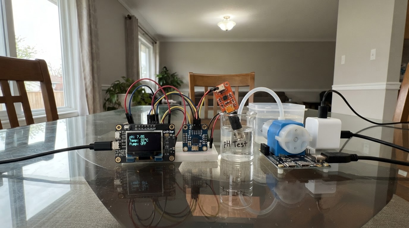
This guide builds a pH monitoring and dosing system using the DFRobot Unihiker K10 microcontroller paired with a precision analog pH sensor and peristaltic pump. The system reads pH values through a high-resolution ADS1115 ADC module and automatically dispenses reagent to adjust pH toward a target setpoint, making it suitable for aquaculture, hydroponics, or laboratory automation.
The guide provides a complete wiring diagram showing how to connect the pH sensor to the ADS1115 module, wire the peristaltic pump control line and power supply, and configure the K10's I2C and GPIO pins. You'll also receive the full firmware with calibration routines, filtered pH readings, PWM pump control using DFRobot's PPM protocol, and operator-controlled dosing functions to get your system up and running.
Wiring diagram

Gather all the parts
Assemble it in 4 steps
1. Keep the two power paths separate
Power the UNIHIKER K10 through its normal USB-C port. Use the separate regulated 5 V, at-least-2 A supply only for the DFR0523 pump. Do not power the pump from a K10 3.3 V, GPIO, or USB connector.
- Keep the pump supply switched off while making signal wiring.
- Use chemically compatible tubing and place the titrant intake tube in the reagent bottle before energizing the pump.
- Liquids and electronics must be physically separated; mount the K10 and ADS1115 above the liquid level.
- An undersized pump supply can reset the K10 or make doses inaccurate.
2. Wire the external ADS1115 pH measurement path
Power both the SEN0161-V2 transmitter and ADS1115 from K10 3V3, and connect both GND pins to K10 GND. Connect SEN0161-V2 AOUT only to ADS1115 AIN0. Connect ADS1115 SDA to K10 SDA / GPIO47 and ADS1115 SCL to K10 SCL / GPIO48. Leave ADS1115 ADDR and ALRT unconnected; this selects I2C address 0x48.
- Use a 3.3 V-compatible ADS1115 breakout. Its I2C pull-up resistors must pull to 3.3 V, not 5 V.
- Keep AOUT-to-AIN0 short and away from the pump motor and supply wires.
- AIN1-AIN3 remain available for future low-voltage sensors but are not used by this instrument.
- Do not connect pH AOUT to K10 P0/GPIO1 anymore; it now goes exclusively to ADS1115 AIN0.
- SEN0161-V2 AOUT is 0-3.0 V. Do not connect a 0-5 V pH transmitter to the ADS1115 when it is powered at 3.3 V.
- Never power a 3.3 V ADS1115/I2C bus from 5 V.
3. Wire the pump supply, common ground, and control
Connect the separate supply +5 V to DFR0523 VCC. Connect its GND to the supply GND and to K10 GND, creating the required common reference. Connect DFR0523 SIG to K10 P1 (GPIO2).
- The common ground is essential: without it the 3.3 V control pulses have no valid reference.
- With power off, arrange tubing so the firmware's clockwise command carries reagent from bottle into sample vessel.
- DFR0523 is a 5-6 V pump system: never connect it to 12 V.
- Do not reverse VCC/GND supply polarity.
4. Verify the ADS1115, calibrate, and make operator-controlled doses
Power the K10. The display must report “ADS1115 OK”; if it says it is not found, disconnect power and inspect 3V3, GND, SDA/GPIO47, and SCL/GPIO48. With the rinsed electrode in stable pH 7.00 buffer, wait for the ADS1115 millivolt reading to settle and press K10 button A. Rinse, place it in pH 4.00 buffer, wait, then press A again. After calibration, put the probe in the stirred sample. Button B sends one 100 ms pump pulse; mix thoroughly and wait for the reading to settle before another pulse.
- Run the pump into a graduated cylinder for a timed sequence and record actual delivered volume; nominal pump flow is not a calibration.
- The default endpoint is pH 7.00 with ±0.05 pH lockout. Confirm this is the validated endpoint for the real titration method.
- Rinse the electrode with deionized water between buffer/sample measurements and blot gently rather than wiping.
- This is intentionally not unattended automatic dosing: reagent concentration, chemistry, sample volume, stirring, and endpoint method must be validated by the operator.
- Wear appropriate PPE and follow the chemical safety information for the acid/base reagent.
Review all connections
1. Connections between "ph_sensor" and "ESP32"
2. Connections between "dosing_pump" and "ESP32"
3. Connections between "pump_supply" and "ESP32"
4. Connections between "ads1115_adc" and "ESP32"
Deploy the firmware
#include <Arduino.h>
#include <Wire.h>
#include <math.h>
#include <Adafruit_ADS1X15.h>
#include "unihiker_k10.h"

// Hardware wiring:
// SEN0161-V2 AOUT -> ADS1115 AIN0; ADS1115 SDA/SCL -> K10 GPIO47/GPIO48.
// K10 P1/GPIO2 -> DFR0523 SIG.

uint32_t pulseToDuty(uint16_t pulseUs);
void setPumpPulse(uint16_t pulseUs);
void stopPump();
float readFilteredMillivolts();
void updateCalibration();
float convertMillivoltsToPh(float millivolts);
String padded(const String &text);
void renderIfChanged();
void captureCalibrationPoint();
void requestDose();

constexpr uint8_t PUMP_PIN = 2;
constexpr uint8_t I2C_SDA_PIN = 47;
constexpr uint8_t I2C_SCL_PIN = 48;
constexpr uint8_t PH_ADC_CHANNEL = 0;
constexpr uint8_t PUMP_PWM_CHANNEL = 0;
constexpr uint8_t PUMP_PWM_BITS = 16;
constexpr uint32_t PUMP_PWM_HZ = 50;
constexpr uint16_t PUMP_PERIOD_US = 20000;

// ADS1115 GAIN_ONE has a +/-4.096 V full-scale range, or 0.125 mV/bit.
// The pH transmitter is powered from 3.3 V and specified to output 0-3.0 V.
constexpr float ADS1115_MV_PER_COUNT = 0.125f;
constexpr uint8_t ADS1115_ADDRESS = 0x48;

// DFRobot DFR0523 PPM protocol: 500-1400 us CW, 1400-1600 us stop,
// 1600-2500 us CCW. Orient tubing so CW moves reagent to the sample.
constexpr uint16_t PUMP_CW_US = 500;
constexpr uint16_t PUMP_STOP_US = 1500;
constexpr uint32_t DOSE_PULSE_MS = 100;
constexpr float TARGET_PH = 7.00f;
constexpr float ENDPOINT_BAND = 0.05f;
constexpr uint8_t SAMPLE_COUNT = 21;
constexpr uint32_t SAMPLE_INTERVAL_MS = 500;

UNIHIKER_K10 k10;
Adafruit_ADS1115 phAdc;

float lastMillivolts = NAN;
float ph7Millivolts = NAN;
float ph4Millivolts = NAN;
float measuredPh = NAN;
bool adcOnline = false;
bool calibrated = false;
bool doseActive = false;
uint32_t doseStartedMs = 0;
uint32_t lastSampleMs = 0;
bool previousButtonA = false;
bool previousButtonB = false;
String statusLine = "Starting ADS1115...";
String previousScreen = "";

uint32_t pulseToDuty(uint16_t pulseUs) {
  const uint32_t maxDuty = (1UL << PUMP_PWM_BITS) - 1UL;
  return (static_cast<uint32_t>(pulseUs) * maxDuty) / PUMP_PERIOD_US;
}

void setPumpPulse(uint16_t pulseUs) {
  ledcWrite(PUMP_PWM_CHANNEL, pulseToDuty(pulseUs));
}

void stopPump() {
  setPumpPulse(PUMP_STOP_US);
  doseActive = false;
}

float readFilteredMillivolts() {
  if (!adcOnline) {
    return NAN;
  }

  int16_t samples[SAMPLE_COUNT];
  for (uint8_t i = 0; i < SAMPLE_COUNT; ++i) {
    samples[i] = phAdc.readADC_SingleEnded(PH_ADC_CHANNEL);
  }

  // Sort then discard the three highest and three lowest samples.
  for (uint8_t i = 0; i < SAMPLE_COUNT - 1; ++i) {
    for (uint8_t j = i + 1; j < SAMPLE_COUNT; ++j) {
      if (samples[j] < samples[i]) {
        const int16_t temp = samples[i];
        samples[i] = samples[j];
        samples[j] = temp;
      }
    }
  }

  int32_t total = 0;
  for (uint8_t i = 3; i < SAMPLE_COUNT - 3; ++i) {
    total += samples[i];
  }
  const float averageCounts = static_cast<float>(total) / static_cast<float>(SAMPLE_COUNT - 6);
  return averageCounts * ADS1115_MV_PER_COUNT;
}

void updateCalibration() {
  calibrated = isfinite(ph7Millivolts) && isfinite(ph4Millivolts) &&
               fabsf(ph4Millivolts - ph7Millivolts) >= 20.0f;
}

float convertMillivoltsToPh(float millivolts) {
  if (!calibrated || !isfinite(millivolts)) {
    return NAN;
  }
  const float slope = (4.00f - 7.00f) / (ph4Millivolts - ph7Millivolts);
  return 7.00f + slope * (millivolts - ph7Millivolts);
}

String padded(const String &text) {
  String result = text;
  while (result.length() < 31) {
    result += ' ';
  }
  return result;
}

void renderIfChanged() {
  const String phText = calibrated && isfinite(measuredPh) ? String(measuredPh, 2) : "--.--";
  const String adcText = isfinite(lastMillivolts) ? String(lastMillivolts, 1) : "--.-";
  const String adcState = adcOnline ? "ADS1115 OK" : "ADS1115 NOT FOUND";
  const String screen = "pH TITRATOR\n"
                        "pH: " + phText + " target: " + String(TARGET_PH, 2) + "\n"
                        "ADC: " + adcText + " mV " + adcState + "\n"
                        "7.00: " + (isfinite(ph7Millivolts) ? String(ph7Millivolts, 1) : String("not saved")) + " mV\n"
                        "4.00: " + (isfinite(ph4Millivolts) ? String(ph4Millivolts, 1) : String("not saved")) + " mV\n"
                        "Pump: " + String(doseActive ? "DOSING" : "STOPPED") + "\n" + statusLine;
  if (screen == previousScreen) {
    return;
  }
  previousScreen = screen;

  k10.canvas->canvasText(padded("pH TITRATOR"), 1, 0x0000FF);
  k10.canvas->canvasText(padded("pH: " + phText + " Target: " + String(TARGET_PH, 2)), 2, 0x000000);
  k10.canvas->canvasText(padded("ADC: " + adcText + " mV " + adcState), 3, adcOnline ? 0x000000 : 0xFF0000);
  k10.canvas->canvasText(padded("7.00: " + (isfinite(ph7Millivolts) ? String(ph7Millivolts, 1) : String("not saved")) + " mV"), 4, 0x000000);
  k10.canvas->canvasText(padded("4.00: " + (isfinite(ph4Millivolts) ? String(ph4Millivolts, 1) : String("not saved")) + " mV"), 5, 0x000000);
  k10.canvas->canvasText(padded("Pump: " + String(doseActive ? "DOSING" : "STOPPED")), 6, doseActive ? 0xFF0000 : 0x008000);
  k10.canvas->canvasText(padded(statusLine), 7, 0x000000);
  k10.canvas->canvasText(padded("A=calibrate  B=100ms dose"), 8, 0x666666);
  k10.canvas->updateCanvas();
}

void captureCalibrationPoint() {
  if (!adcOnline || !isfinite(lastMillivolts)) {
    statusLine = "ADS1115 unavailable; check I2C wiring";
    return;
  }
  if (!isfinite(ph7Millivolts)) {
    ph7Millivolts = lastMillivolts;
    statusLine = "pH 7.00 saved; rinse, then pH 4.00";
  } else {
    ph4Millivolts = lastMillivolts;
    updateCalibration();
    statusLine = calibrated ? "Calibrated: B doses 100 ms" : "Calibration failed; repeat pH 7 then pH 4";
    if (!calibrated) {
      ph7Millivolts = NAN;
      ph4Millivolts = NAN;
    }
  }
}

void requestDose() {
  if (!adcOnline) {
    statusLine = "ADS1115 unavailable; pump locked";
    return;
  }
  if (!calibrated) {
    statusLine = "Calibrate pH 7 then pH 4 first";
    return;
  }
  if (isfinite(measuredPh) && fabsf(measuredPh - TARGET_PH) <= ENDPOINT_BAND) {
    statusLine = "Endpoint band reached; pump locked";
    return;
  }
  setPumpPulse(PUMP_CW_US);
  doseStartedMs = millis();
  doseActive = true;
  statusLine = "Dosing 100 ms; mix before next dose";
}

void setup() {
  Serial.begin(115200);
  k10.begin();
  k10.initScreen(2);
  k10.creatCanvas();
  k10.setScreenBackground(0xFFFFFF);

  Wire.begin(I2C_SDA_PIN, I2C_SCL_PIN);
  adcOnline = phAdc.begin(ADS1115_ADDRESS, &Wire);
  if (adcOnline) {
    phAdc.setGain(GAIN_ONE);
    statusLine = "ADS1115 ready; A captures pH 7";
    lastMillivolts = readFilteredMillivolts();
  } else {
    statusLine = "ADS1115 missing: check SDA/SCL";
  }

  ledcSetup(PUMP_PWM_CHANNEL, PUMP_PWM_HZ, PUMP_PWM_BITS);
  ledcAttachPin(PUMP_PIN, PUMP_PWM_CHANNEL);
  stopPump();
  renderIfChanged();
}

void loop() {
  const uint32_t now = millis();
  if (doseActive && (now - doseStartedMs >= DOSE_PULSE_MS)) {
    stopPump();
  }
  if (adcOnline && now - lastSampleMs >= SAMPLE_INTERVAL_MS) {
    lastSampleMs = now;
    lastMillivolts = readFilteredMillivolts();
    measuredPh = convertMillivoltsToPh(lastMillivolts);
  }

  const bool buttonA = k10.buttonA->isPressed();
  const bool buttonB = k10.buttonB->isPressed();
  if (buttonA && !previousButtonA && !doseActive) {
    captureCalibrationPoint();
  }
  if (buttonB && !previousButtonB) {
    if (doseActive) {
      stopPump();
      statusLine = "Dose cancelled";
    } else {
      requestDose();
    }
  }
  previousButtonA = buttonA;
  previousButtonB = buttonB;
  renderIfChanged();
  delay(10);
}
Remix this project
Make it yours in one click
Open a full copy of this project in your own Schematik workspace — diagram, code, parts, and assembly steps included. Swap the sensor, add features, or redesign the whole thing with AI. The author's original stays untouched.