Community project
Using A Waveshare Esp32-s3-eth Board I Want To
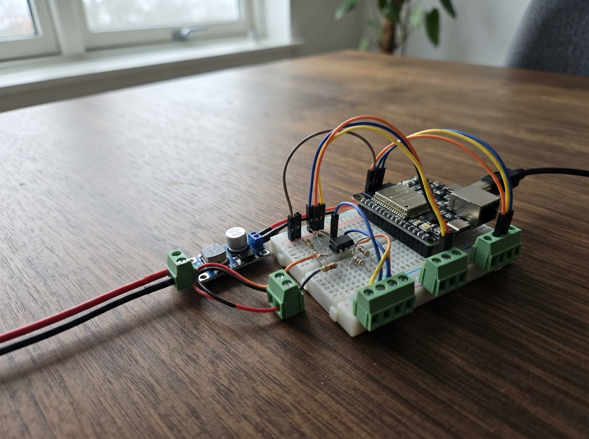
This guide builds a pulse and encoder monitoring system using the Waveshare ESP32-S3-ETH board with isolated gate-driver control. The project captures incoming pulse widths and encoder edges over Ethernet, making it suitable for industrial automation, motor control feedback, or precision timing applications where electrical isolation is critical.
The guide provides a complete wiring diagram, parts list, and step-by-step assembly instructions for integrating the 24V buck converter, HCPL-3150 optocoupler isolation, and screw terminal connections. Firmware is included to handle real-time pulse capture, encoder counting, and TCP command processing on port 5000.
Wiring diagram

Gather all the parts
Assemble it in 9 steps
1. Keep everything unpowered while wiring
Place the Waveshare ESP32-S3-ETH board, LM2596 converter, HCPL-3150, 180 Ω resistor, and terminals where you can reach them. Leave USB and both DC supplies disconnected while making the connections.
- Put the HCPL-3150 across the middle gap of a breadboard so its two sides are separated.
- Do not move wires while power is connected; a loose wire can short power and damage the board or converter.
2. Connect the incoming pulse
Connect the external pulse source signal wire to the pulse-input terminal, then connect its SIG wire to GPIO40 (signal). Connect the source return wire to terminal GND and a board GND pin (ground) so both devices share the same electrical reference.
- GPIO40 accepts a 3.3 V logic signal: low is near 0 V and high is near 3.3 V.
- Do not connect a 5 V pulse directly to GPIO40 — it can damage the ESP32-S3. Use a level shifter or divider that makes the GPIO40 signal no higher than 3.3 V.
3. Connect encoder channel A
Connect the encoder channel-A signal wire to terminal A, then connect that terminal to GPIO38 (signal). Connect the encoder ground or signal-return wire to terminal GND and a board GND pin (ground).
- This build counts rising edges on channel A only while the GPIO40 input pulse is high.
- Do not connect a 5 V encoder output directly to GPIO38 — reduce it to a 3.3 V logic signal first, or use a 3.3 V encoder.
4. Wire the HCPL-3150 input side
Connect GPIO41 to one lead of the 180 Ω resistor (signal). Connect the resistor’s other lead to HCPL-3150 pin 1, the anode (signal). Connect HCPL-3150 pin 2, the cathode, to an ESP32 GND pin (ground).
- The resistor limits the LED current inside the HCPL-3150. The dot or notch on the chip identifies pin 1.
- Do not connect the HCPL-3150 input LED directly to GPIO41 — without the resistor the GPIO pin or optocoupler can be damaged.
5. Wire the isolated HCPL-3150 output side
Connect the isolated 15 V supply terminal +15V to HCPL-3150 pin 8, VCC (power). Connect the isolated supply 0V to pin 5, VEE (ground). Fit the 0.1 µF capacitor directly between pins 8 and 5 (power smoothing). Connect HCPL-3150 pin 6, VO, to output-terminal OUT (output signal), and connect output-terminal GND to pin 5, VEE (output return).
- Keep the capacitor leads short and close to pins 8 and 5; it helps the driver make clean output pulses.
- The HCPL-3150 output side requires a separate 15 V supply. Do not connect its VCC pin to the ESP32 3.3 V or 5 V rails. Keep the isolated 15 V 0V wire separate from ESP32 GND unless the external equipment design specifically requires them joined.
6. Wire the LM2596 input
Connect the external DC supply positive wire to the DC-supply terminal VIN+ (power), then connect that terminal to LM2596 VIN+ (power). Connect the external supply negative wire to terminal GND (ground), then connect it to LM2596 VIN- (ground).
- The supply voltage must be higher than 5 V for this step-down converter to regulate correctly.
- Observe positive and negative markings carefully — reversing the input supply can destroy the LM2596 module and board. Do not connect mains electricity directly to this terminal.
7. Set the converter to exactly 5 V
Power only the LM2596 input from the external DC supply. Use a multimeter across LM2596 VOUT+ and VOUT- and turn the adjustment screw until it reads 5.0 V. Disconnect the external DC supply again after adjustment.
- Set and measure the output before connecting it to the ESP32 board.
- Do not connect the LM2596 output to VSYS until the meter shows 5.0 V. A higher setting can damage the board.
8. Feed the board from the adjusted converter
Connect LM2596 VOUT+ to the board header pin labelled VSYS, physical pin 39 (5 V power). Connect LM2596 VOUT- to any board GND pin (ground).
- The LM2596 output ground also provides the shared ground for the board and the external input signal equipment.
- Do not connect USB power and the LM2596 VSYS supply at the same time unless your exact board revision documentation explicitly permits it.
9. Attach Ethernet and power the two supplies
Plug a network cable into the RJ45 socket. Apply the adjusted board supply and the separate isolated 15 V HCPL-3150 supply. The board requests a network address automatically and listens for TCP commands on port 5000.
- Send LIMITS 100 2000 as an example to allow pulses from 100 to 2,000 microseconds; replace those numbers with your allowed range.
- Make sure every external signal connected directly to GPIO40 or GPIO38 shares ESP32 GND. The HCPL-3150 output-side 0V is deliberately separate for isolation.
Review all connections
1. Connections between "pulse_input_terminal" and "ESP32"
2. Connections between "encoder_input_terminal" and "ESP32"
3. Connections between "vsys_power_terminal" and "ESP32"
4. Connections between "lm2596_converter" and "ESP32"
5. Connections between "output_terminal" and "ESP32"
6. Connections between "hcpl3150_input_resistor" and "ESP32"
7. Connections between "hcpl3150_driver" and "ESP32"
8. Connections between "hcpl3150_supply_terminal" and "ESP32"
9. Connections between "hcpl3150_bypass_capacitor" and "ESP32"
Deploy the firmware
#include <Arduino.h>
#include <SPI.h>
#include <Ethernet.h>

void IRAM_ATTR onEncoderARising();
void IRAM_ATTR onPulseChange();
void sendLine(EthernetClient &client, const String &line);
void processCommand(String command, EthernetClient &client);
void serviceTcp();
void reportCapturedPulse();

constexpr uint8_t PULSE_INPUT_PIN = 40;
constexpr uint8_t ENCODER_A_PIN = 38;
constexpr uint8_t OUTPUT_PULSE_PIN = 41;
constexpr uint8_t ETH_MISO_PIN = 12;
constexpr uint8_t ETH_MOSI_PIN = 11;
constexpr uint8_t ETH_SCK_PIN = 13;
constexpr uint8_t ETH_CS_PIN = 14;
constexpr uint16_t TCP_PORT = 5000;
constexpr uint32_t OUTPUT_PULSE_WIDTH_US = 1000;

byte macAddress[] = {0x02, 0x53, 0x45, 0x54, 0x48, 0x01};
EthernetServer server(TCP_PORT);

volatile uint32_t encoderEdgeCount = 0;
volatile uint32_t pulseStartUs = 0;
volatile uint32_t pulseStartEncoderCount = 0;
volatile uint32_t capturedPulseWidthUs = 0;
volatile uint32_t capturedEncoderEdges = 0;
volatile bool pulseCaptured = false;
volatile bool pulseHigh = false;

uint32_t minWidthUs = 0;
uint32_t maxWidthUs = 0;
bool limitsConfigured = false;
bool outputPulseActive = false;
uint32_t outputPulseStartedUs = 0;

void IRAM_ATTR onEncoderARising() { encoderEdgeCount++; }

void IRAM_ATTR onPulseChange() {
  const uint32_t now = micros();
  if (digitalRead(PULSE_INPUT_PIN) == HIGH) {
    pulseStartUs = now;
    pulseStartEncoderCount = encoderEdgeCount;
    pulseHigh = true;
  } else if (pulseHigh) {
    capturedPulseWidthUs = now - pulseStartUs;
    capturedEncoderEdges = encoderEdgeCount - pulseStartEncoderCount;
    pulseHigh = false;
    pulseCaptured = true;
  }
}

void sendLine(EthernetClient &client, const String &line) {
  client.print(line);
  client.print("\r\n");
}

void processCommand(String command, EthernetClient &client) {
  command.trim();
  command.toUpperCase();
  if (command == "GET LIMITS") {
    sendLine(client, limitsConfigured ? "LIMITS " + String(minWidthUs) + " " + String(maxWidthUs) : "LIMITS NOT_SET");
    return;
  }
  if (command == "GET STATUS") {
    sendLine(client, String("STATUS LIMITS=") + (limitsConfigured ? "SET" : "NOT_SET") + " MIN_US=" + String(minWidthUs) + " MAX_US=" + String(maxWidthUs));
    return;
  }
  unsigned long requestedMin = 0;
  unsigned long requestedMax = 0;
  if (sscanf(command.c_str(), "LIMITS %lu %lu", &requestedMin, &requestedMax) == 2) {
    if (requestedMin > 0 && requestedMin <= requestedMax) {
      minWidthUs = requestedMin;
      maxWidthUs = requestedMax;
      limitsConfigured = true;
      sendLine(client, "OK LIMITS " + String(minWidthUs) + " " + String(maxWidthUs));
    } else {
      sendLine(client, "ERROR limits must be positive and MIN_US must not exceed MAX_US");
    }
    return;
  }
  sendLine(client, "ERROR commands: LIMITS <min_us> <max_us>, GET LIMITS, GET STATUS");
}

void serviceTcp() {
  EthernetClient client = server.available();
  if (!client) return;
  client.setTimeout(1000);
  sendLine(client, "PULSE_GATE READY");
  processCommand(client.readStringUntil('\n'), client);
  delay(2);
  client.stop();
}

void reportCapturedPulse() {
  uint32_t widthUs;
  uint32_t encoderEdges;
  noInterrupts();
  widthUs = capturedPulseWidthUs;
  encoderEdges = capturedEncoderEdges;
  pulseCaptured = false;
  interrupts();
  const bool accepted = limitsConfigured && widthUs >= minWidthUs && widthUs <= maxWidthUs;
  if (accepted && !outputPulseActive) {
    digitalWrite(OUTPUT_PULSE_PIN, HIGH);
    outputPulseStartedUs = micros();
    outputPulseActive = true;
  }
  Serial.printf("PULSE width_us=%lu encoder_a_edges=%lu result=%s\n", static_cast<unsigned long>(widthUs), static_cast<unsigned long>(encoderEdges), accepted ? "ACCEPTED" : "REJECTED");
}

void setup() {
  Serial.begin(115200);
  pinMode(PULSE_INPUT_PIN, INPUT_PULLDOWN);
  pinMode(ENCODER_A_PIN, INPUT_PULLDOWN);
  pinMode(OUTPUT_PULSE_PIN, OUTPUT);
  digitalWrite(OUTPUT_PULSE_PIN, LOW);
  attachInterrupt(digitalPinToInterrupt(ENCODER_A_PIN), onEncoderARising, RISING);
  attachInterrupt(digitalPinToInterrupt(PULSE_INPUT_PIN), onPulseChange, CHANGE);
  SPI.begin(ETH_SCK_PIN, ETH_MISO_PIN, ETH_MOSI_PIN, ETH_CS_PIN);
  Ethernet.init(ETH_CS_PIN);
  Ethernet.begin(macAddress);
  server.begin();
  Serial.print("TCP pulse gate listening on port ");
  Serial.println(TCP_PORT);
  Serial.print("Ethernet IP: ");
  Serial.println(Ethernet.localIP());
}

void loop() {
  serviceTcp();
  if (pulseCaptured) reportCapturedPulse();
  if (outputPulseActive && static_cast<uint32_t>(micros() - outputPulseStartedUs) >= OUTPUT_PULSE_WIDTH_US) {
    digitalWrite(OUTPUT_PULSE_PIN, LOW);
    outputPulseActive = false;
  }
}
Remix this project
Make it yours in one click
Open a full copy of this project in your own Schematik workspace — diagram, code, parts, and assembly steps included. Swap the sensor, add features, or redesign the whole thing with AI. The author's original stays untouched.