Community project
Voice-Controlled Smart Switches
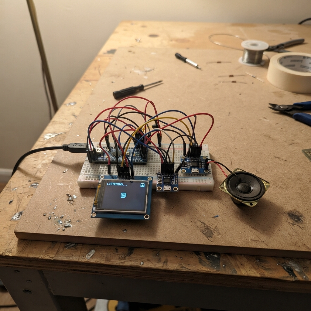
This project builds a voice-controlled smart switch system using an ESP32 microcontroller to recognize spoken commands and trigger remote actions. The system combines a small TFT display for visual feedback, an I²S microphone for capturing voice input, and an amplifier with speaker for audio output, all working together to process voice commands and communicate with remote switch receivers via ESP-NOW wireless protocol.
The guide provides a complete wiring diagram showing how to connect the display, microphone module, amplifier, and speaker to the ESP32, along with a parts list, firmware with voice recognition capabilities, and step-by-step assembly instructions. Builders will learn how to set up I²S audio peripherals, integrate voice wake-word and command recognition, and establish wireless communication to control lights and fans remotely.
Wiring diagram
Gather all the parts
Assemble it in 5 steps
1. Place the S3 board and keep USB accessible
Put the ESP32-S3-DevKitC-1 where its USB connector stays accessible. Use its USB connection for the assistant board’s power and later flashing.
- Do not connect the separate 5 V servo supply to this ESP32-S3 board.
- Do not use the ESP32-S3 3V3 pin to power the servo motors; that can damage the board.
2. Wire the small display
Connect the ST7735 display: VCC → 3V3 (power), GND → GND (ground), SCK → GPIO12 (screen timing), MOSI/SDA → GPIO11 (screen data), CS → GPIO10 (screen select), DC/A0 → GPIO14 (screen command/data selection), RST/RES → GPIO15 (screen reset), and BL/LED → GPIO16 (screen backlight control).
- Check the labels printed on your display board; some boards label MOSI as SDA and DC as A0.
- Make sure VCC and GND are not swapped — swapped power can damage the screen.
3. Wire the microphone
Connect the INMP441 microphone: VDD → 3V3 (power), GND → GND (ground), SCK → GPIO4 (audio timing), WS → GPIO5 (audio timing), SD → GPIO6 (microphone sound data), and L/R → GND (selects the left microphone channel used by the firmware).
- Keep these audio wires short and route them away from the speaker wires to reduce unwanted noise.
- Only use the 3V3 pin for the microphone; connecting it to 5 V can damage the module.
4. Wire the amplifier and speaker
Connect the MAX98357A amplifier: VIN → 3V3 (power), GND → GND (ground), BCLK → the INMP441 SCK pin (shared audio timing), LRC → the INMP441 WS pin (shared audio timing), and DIN → GPIO7 (sound data going to the amplifier). Connect the speaker’s two wires to SPK+ and SPK− on the amplifier (speaker output).
- The two speaker wires go only to SPK+ and SPK−; speaker polarity only changes the phase for one speaker, not whether it works.
- Do not connect either speaker wire to GND — the amplifier drives both speaker terminals and grounding one can damage it.
5. Prepare the separate servo receiver
Keep the ESP32-DEVKIT-V1, four SG90 servos, and the separate regulated 5 V servo supply together for the second receiver-board project. Join the servo supply GND to the ESP32-DEVKIT-V1 GND so its control signals have the same reference.
- The receiver board must be flashed with its own firmware because it is a separate ESP32.
- Do not power four SG90 servos from either ESP32 board’s 5 V or 3V3 pin; motor movement can draw enough current to reset or damage the board.
Review all connections
1. Connections between "tft_1" and "ESP32"
2. Connections between "mic_1" and "ESP32"
3. Connections between "amp_1" and "ESP32"
Deploy the firmware
#include <string.h>
#include "freertos/FreeRTOS.h"
#include "freertos/task.h"
#include "driver/gpio.h"
#include "driver/spi_master.h"
#include "driver/i2s_std.h"
#include "esp_event.h"
#include "esp_wifi.h"
#include "esp_now.h"
#include "esp_netif.h"
#include "nvs_flash.h"
#include "esp_heap_caps.h"
#include "esp_wn_iface.h"
#include "esp_wn_models.h"
#include "esp_mn_iface.h"
#include "esp_mn_models.h"
#include "esp_mn_commands.h"
#include "esp_srmodel.h"

#define TFT_CS 10
#define TFT_DC 14
#define TFT_RST 15
#define TFT_BL 16
#define TFT_SCLK 12
#define TFT_MOSI 11
#define I2S_BCLK 4
#define I2S_WS 5
#define I2S_MIC_DIN 6
#define I2S_AMP_DOUT 7

typedef enum { LIGHT_ON = 1, LIGHT_OFF, FAN_ON, FAN_OFF } action_t;
typedef struct __attribute__((packed)) { uint8_t action; uint8_t sequence; } now_packet_t;
static const uint8_t BCAST[6]={255,255,255,255,255,255};
static spi_device_handle_t display;
static i2s_chan_handle_t i2s_rx,i2s_tx;

static void spi_write(bool data,const uint8_t *bytes,size_t length){gpio_set_level(TFT_DC,data);spi_transaction_t tx={.length=length*8,.tx_buffer=bytes};spi_device_polling_transmit(display,&tx);}
static void command(uint8_t c){spi_write(false,&c,1);}
static void data(const uint8_t *p,size_t n){spi_write(true,p,n);}
static void window(uint8_t x,uint8_t y,uint8_t w,uint8_t h){uint8_t a[]={0,x,0,(uint8_t)(x+w-1)},b[]={0,y,0,(uint8_t)(y+h-1)};command(0x2A);data(a,4);command(0x2B);data(b,4);command(0x2C);}
static void box(uint8_t x,uint8_t y,uint8_t w,uint8_t h,uint16_t c){uint8_t p[]={c>>8,c};window(x,y,w,h);for(int i=0;i<w*h;i++)data(p,2);}
static void dashboard(action_t active,bool listening){static int old=-1;static bool was=false;if(old==active&&was==listening)return;old=active;was=listening;box(0,0,128,160,0x0842);box(0,0,128,32,listening?0x07E0:0x001F);for(int i=0;i<4;i++){uint8_t x=(i&1)?66:4,y=(i>1)?90:47;uint16_t c=active==i+1?(listening?0xFFE0:0x07E0):0x2104;box(x,y,58,37,c);box(x+3,y+3,52,31,0x1082);}}
static void display_init(void){gpio_config_t g={.pin_bit_mask=(1ULL<<TFT_DC)|(1ULL<<TFT_RST)|(1ULL<<TFT_BL),.mode=GPIO_MODE_OUTPUT};gpio_config(&g);gpio_set_level(TFT_BL,1);gpio_set_level(TFT_RST,0);vTaskDelay(pdMS_TO_TICKS(20));gpio_set_level(TFT_RST,1);vTaskDelay(pdMS_TO_TICKS(120));spi_bus_config_t bus={.sclk_io_num=TFT_SCLK,.mosi_io_num=TFT_MOSI,.miso_io_num=-1,.max_transfer_sz=512};spi_device_interface_config_t dev={.clock_speed_hz=20000000,.mode=0,.spics_io_num=TFT_CS,.queue_size=1};spi_bus_initialize(SPI2_HOST,&bus,SPI_DMA_CH_AUTO);spi_bus_add_device(SPI2_HOST,&dev,&display);command(0x01);vTaskDelay(pdMS_TO_TICKS(150));command(0x11);vTaskDelay(pdMS_TO_TICKS(120));uint8_t m=0xC8,f=0x05;command(0x36);data(&m,1);command(0x3A);data(&f,1);command(0x29);}
static void audio_init(void){i2s_chan_config_t c=I2S_CHANNEL_DEFAULT_CONFIG(I2S_NUM_0,I2S_ROLE_MASTER);i2s_new_channel(&c,&i2s_tx,&i2s_rx);i2s_std_config_t r={.clk_cfg=I2S_STD_CLK_DEFAULT_CONFIG(16000),.slot_cfg=I2S_STD_MSB_SLOT_DEFAULT_CONFIG(I2S_DATA_BIT_WIDTH_32BIT,I2S_SLOT_MODE_MONO),.gpio_cfg={.mclk=I2S_GPIO_UNUSED,.bclk=I2S_BCLK,.ws=I2S_WS,.dout=I2S_GPIO_UNUSED,.din=I2S_MIC_DIN}};i2s_std_config_t t={.clk_cfg=I2S_STD_CLK_DEFAULT_CONFIG(16000),.slot_cfg=I2S_STD_MSB_SLOT_DEFAULT_CONFIG(I2S_DATA_BIT_WIDTH_16BIT,I2S_SLOT_MODE_MONO),.gpio_cfg={.mclk=I2S_GPIO_UNUSED,.bclk=I2S_BCLK,.ws=I2S_WS,.dout=I2S_AMP_DOUT,.din=I2S_GPIO_UNUSED}};i2s_channel_init_std_mode(i2s_rx,&r);i2s_channel_init_std_mode(i2s_tx,&t);i2s_channel_enable(i2s_rx);i2s_channel_enable(i2s_tx);}
static void chime(void){int16_t s[1600];for(int i=0;i<1600;i++){int p=(i*880*256/16000)&255;s[i]=((p<128?p:255-p)-64)*170;}size_t n;i2s_channel_write(i2s_tx,s,sizeof(s),&n,portMAX_DELAY);}
static void radio_init(void){nvs_flash_init();esp_netif_init();esp_event_loop_create_default();wifi_init_config_t w=WIFI_INIT_CONFIG_DEFAULT();esp_wifi_init(&w);esp_wifi_set_mode(WIFI_MODE_STA);esp_wifi_start();esp_now_init();esp_now_peer_info_t peer={0};memcpy(peer.peer_addr,BCAST,6);peer.ifidx=WIFI_IF_STA;esp_now_add_peer(&peer);}
static void transmit(action_t action){static uint8_t seq;now_packet_t p={action,++seq};esp_now_send(BCAST,(uint8_t *)&p,sizeof(p));chime();}
static action_t map_command(int id){if(id<1||id>8)return 0;return (action_t)((id-1)/2+1);}
static void voice(void *unused){srmodel_list_t *models=esp_srmodel_init("model");char *wake_model=esp_srmodel_filter(models,ESP_WN_PREFIX,"wn9_alexa");char *command_model=esp_srmodel_filter(models,ESP_MN_PREFIX,NULL);const esp_wn_iface_t *wake=esp_wn_handle_from_name(wake_model);const esp_mn_iface_t *multi=esp_mn_handle_from_name(command_model);model_iface_data_t *wake_data=wake->create(wake_model,DET_MODE_90);model_iface_data_t *multi_data=multi->create(command_model,6000);esp_mn_commands_clear();esp_mn_commands_add(1,"turn on the light");esp_mn_commands_add(2,"light on");esp_mn_commands_add(3,"turn off the light");esp_mn_commands_add(4,"light off");esp_mn_commands_add(5,"turn on the fan");esp_mn_commands_add(6,"fan on");esp_mn_commands_add(7,"turn off the fan");esp_mn_commands_add(8,"fan off");esp_mn_commands_update();int chunk=wake->get_samp_chunksize(wake_data);int16_t *pcm=heap_caps_malloc(chunk*sizeof(int16_t),MALLOC_CAP_SPIRAM|MALLOC_CAP_8BIT);bool armed=false;action_t last=0;dashboard(0,false);while(1){size_t n;i2s_channel_read(i2s_rx,pcm,chunk*sizeof(int16_t),&n,portMAX_DELAY);if(n!=chunk*sizeof(int16_t))continue;if(!armed){if(wake->detect(wake_data,pcm)>0){armed=true;dashboard(last,true);}}else{esp_mn_results_t *result=multi->detect(multi_data,pcm);if(result&&result->num){action_t a=map_command(result->command_id[0]);if(a){last=a;transmit(a);}armed=false;dashboard(last,false);}}}}
void app_main(void){display_init();audio_init();radio_init();xTaskCreatePinnedToCore(voice,"voice",12288,NULL,5,NULL,1);}
Remix this project
Make it yours in one click
Open a full copy of this project in your own Schematik workspace — diagram, code, parts, and assembly steps included. Swap the sensor, add features, or redesign the whole thing with AI. The author's original stays untouched.