Community project
Wi-Fi EV Charging Monitor
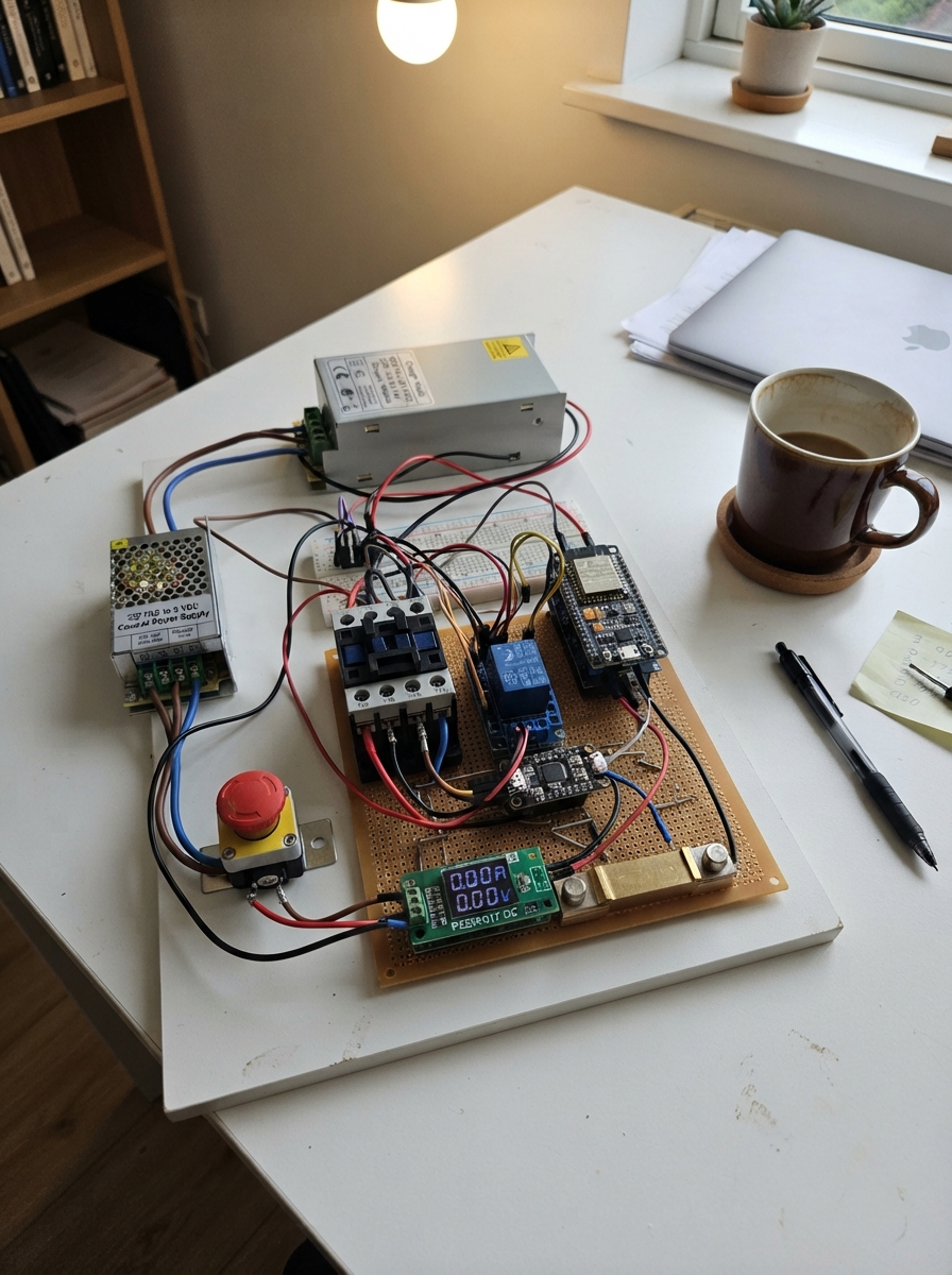
This guide builds a networked EV charging monitor that measures and controls DC charging power over Wi-Fi. The system uses an ESP32 microcontroller to read real-time voltage, current, and energy consumption from a PZEM-017 energy meter via RS485 Modbus, then publishes the data to an MQTT broker. A relay module gates the AC contactor that supplies the charger, allowing remote start/stop control with hardware safety interlocks.
The assembly covers mounting the 220 VAC input and charger module, wiring the high-current DC charging path with the 50 A shunt and energy meter, routing the isolated 5 V control supply, configuring the RS485 transceiver and ESP32 GPIO pins, and verifying all safety chains before commissioning. The included firmware handles Wi-Fi connection, Modbus polling, MQTT publishing, and relay switching with configurable intervals and retry logic.
Wiring diagram

Gather all the parts
Assemble it in 7 steps
1. Mount the mains and charger parts
Place the 220 VAC input terminal block, AC contactor, factory charger, and separate 220 VAC-to-5 V control power supply inside a properly rated closed electrical enclosure. Keep the mains and 84 VDC high-current wiring physically away from the ESP32 and communications wiring.
- 220 VAC can seriously injure or kill. A qualified electrician should make and inspect all mains wiring.
- Do not work on this enclosure while its 220 VAC source is connected.
2. Wire the AC charger power path
Connect input terminal L-CHARGER to the contactor LINE-IN, then connect contactor LOAD-OUT to charger AC-L (switched AC power). Connect input terminal N-CHARGER to charger AC-N (AC neutral). The contactor, not the small relay module, switches the charger’s mains input.
- Use conductors, terminals, enclosure, strain relief, earthing, and protective devices selected by a qualified installer for the actual installation.
- A loose mains terminal can overheat and start a fire. Torque every terminal to its manufacturer’s specification.
3. Wire the DC charging and measurement path
Connect charger DC+ to the 50 A shunt CHARGER-SIDE terminal (high-current positive). Connect shunt BATTERY-SIDE to EV battery BAT+ (high-current positive). Connect charger DC- directly to EV battery BAT- (high-current negative return). Connect the PZEM SHUNT+ and SHUNT- sense leads to the matching small shunt sense terminals, then PZEM METER+ to charger DC+ and PZEM METER- to battery BAT-.
- The large shunt terminals carry charging current; the small sense terminals go only to the PZEM meter.
- The 50 A shunt is above the planned 28 A maximum charge current.
- Reversing battery polarity or using undersized DC cable can damage equipment or create a fire risk.
4. Wire the separate 5 V control supply
Connect input terminal L-CONTROL to the control power supply AC-L and N-CONTROL to AC-N (separate control power). Connect its 5V-OUT to the 5 V rail and GND-OUT to the ground rail. Feed the relay module VCC and GND, and the PZEM 5V-IN and GND, from those rails. The PZEM therefore receives its specified separate 5 V supply rather than an assumed supply.
- Make sure the low-voltage 5 V output terminals are not connected to any 220 VAC terminal — swapped wiring can destroy the control electronics.
5. Wire the contactor coil safety chain
Connect input terminal L-COIL to relay COM, relay NO to Emergency Stop AC-IN, and Emergency Stop AC-OUT to contactor COIL-A1 (coil-control path). Connect input terminal N-COIL to contactor COIL-A2 (coil neutral). With the emergency stop pressed, the coil loses power even if the ESP32 requests charging.
- The relay contacts switch only the 220 VAC contactor coil circuit; never route the 28 A DC battery charging current through this relay module.
6. Wire the ESP32 and RS485 communications
Connect relay IN to ESP32 GPIO27 (relay control signal). Connect the RS485 transceiver TX to GPIO16, RX to GPIO17, DE to GPIO26, and RE to GPIO25 (meter communications). Connect transceiver A to PZEM RS485-A and B to PZEM RS485-B. Connect the transceiver to ESP32 3.3 V and GND; the PZEM remains powered from its separate 5 V rail.
- Keep the RS485 A/B pair twisted and away from mains and the high-current DC leads where possible.
- Do not connect an unverified 5 V-only RS485 module directly to ESP32 GPIO pins — ESP32 pins use 3.3 V logic.
7. Check safety before enabling power
With power still disconnected, check that the emergency stop opens the contactor coil path and that the contactor main terminals feed only the charger AC input. Confirm the PZEM is connected across the DC output and its shunt sense terminals, while the relay is only in the coil-control circuit. Have a qualified person inspect the enclosure before connecting the 220 VAC source.
- This preliminary architecture is not a final electrical installation drawing. Final protection, conductor sizing, earthing, enclosure rating, isolation, and local code compliance require a qualified electrical designer or installer.
Review all connections
1. Connections between "ac_input_terminal_1" and "ESP32"
2. Connections between "ac_contactor_1" and "ESP32"
3. Connections between "factory_dc_charger_1" and "ESP32"
4. Connections between "shunt_50a_1" and "ESP32"
5. Connections between "pzem017_1" and "ESP32"
6. Connections between "control_psu_1" and "ESP32"
7. Connections between "relay_module_1" and "ESP32"
8. Connections between "emergency_stop_1" and "ESP32"
9. Connections between "rs485_transceiver_1" and "ESP32"
Deploy the firmware
#include <Arduino.h>
#include <WiFi.h>

// One EV charger preliminary control firmware. Set these commissioning values before deployment.
static const char *WIFI_SSID = "YOUR_WIFI_SSID";
static const char *WIFI_PASSWORD = "YOUR_WIFI_PASSWORD";
static const char *MQTT_HOST = "192.168.1.10";
static const uint16_t MQTT_PORT = 1883;
static const char *CHARGER_ID = "charger-01";

constexpr uint8_t RELAY_PIN = 27;
constexpr uint8_t RS485_RX_PIN = 16;
constexpr uint8_t RS485_TX_PIN = 17;
constexpr uint8_t RS485_DE_PIN = 26;
constexpr uint8_t RS485_RE_PIN = 25;
constexpr uint8_t PZEM_ADDRESS = 0x01;
constexpr uint32_t PZEM_BAUD = 9600;
constexpr uint32_t POLL_INTERVAL_MS = 1000;
constexpr uint32_t PUBLISH_INTERVAL_MS = 5000;
constexpr uint32_t MQTT_RETRY_MS = 5000;

HardwareSerial rs485Serial(2);
WiFiClient mqttClient;
bool chargingEnabled = false;
bool meterOnline = false;
bool mqttConnected = false;
float dcVoltage = 0.0F;
float dcCurrent = 0.0F;
float dcPower = 0.0F;
float energyKwh = 0.0F;
uint32_t sessionStartedMs = 0;
uint32_t lastPollMs = 0;
uint32_t lastPublishMs = 0;
uint32_t lastMqttAttemptMs = 0;

uint16_t modbusCrc(const uint8_t *data, size_t length) {
  uint16_t crc = 0xFFFF;
  for (size_t i = 0; i < length; ++i) {
    crc ^= data[i];
    for (uint8_t bit = 0; bit < 8; ++bit) {
      crc = (crc & 1U) ? (crc >> 1U) ^ 0xA001U : crc >> 1U;
    }
  }
  return crc;
}

void rs485TransmitEnable() {
  digitalWrite(RS485_RE_PIN, HIGH);
  digitalWrite(RS485_DE_PIN, HIGH);
}

void rs485ReceiveEnable() {
  digitalWrite(RS485_DE_PIN, LOW);
  digitalWrite(RS485_RE_PIN, LOW);
}

void setCharging(bool enabled) {
  chargingEnabled = enabled;
  // This output drives only the relay input, which switches the AC contactor coil.
  digitalWrite(RELAY_PIN, enabled ? HIGH : LOW);
  if (enabled) {
    sessionStartedMs = millis();
  }
}

bool mqttWriteString(const char *value) {
  uint16_t length = strlen(value);
  uint8_t prefix[2] = {static_cast<uint8_t>(length >> 8), static_cast<uint8_t>(length)};
  return mqttClient.write(prefix, sizeof(prefix)) == sizeof(prefix) &&
         mqttClient.write(reinterpret_cast<const uint8_t *>(value), length) == length;
}

bool mqttConnect() {
  if (WiFi.status() != WL_CONNECTED || strcmp(WIFI_SSID, "YOUR_WIFI_SSID") == 0) return false;
  if (!mqttClient.connect(MQTT_HOST, MQTT_PORT)) return false;

  String clientId = String("esp32-") + CHARGER_ID;
  const uint16_t remaining = 10 + 2 + clientId.length();
  uint8_t fixed[5] = {0x10, static_cast<uint8_t>(remaining), 0x00, 0x04, 'M'};
  if (mqttClient.write(fixed, sizeof(fixed)) != sizeof(fixed) ||
      mqttClient.write(reinterpret_cast<const uint8_t *>("QTT"), 3) != 3) return false;
  uint8_t connectFlags[] = {0x04, 0x02, 0x00, 0x3C};
  if (mqttClient.write(connectFlags, sizeof(connectFlags)) != sizeof(connectFlags) ||
      !mqttWriteString(clientId.c_str())) return false;

  uint32_t started = millis();
  while (mqttClient.available() < 4 && millis() - started < 1500) delay(5);
  uint8_t response[4];
  if (mqttClient.readBytes(response, sizeof(response)) != sizeof(response) ||
      response[0] != 0x20 || response[1] != 0x02 || response[3] != 0x00) {
    mqttClient.stop();
    return false;
  }

  String topic = String("evcharger/") + CHARGER_ID + "/command";
  uint16_t topicLength = topic.length();
  uint16_t subscribeLength = 2 + 2 + topicLength + 1;
  uint8_t header[] = {0x82, static_cast<uint8_t>(subscribeLength), 0x00, 0x01,
                      static_cast<uint8_t>(topicLength >> 8), static_cast<uint8_t>(topicLength)};
  if (mqttClient.write(header, sizeof(header)) != sizeof(header) ||
      mqttClient.write(reinterpret_cast<const uint8_t *>(topic.c_str()), topicLength) != topicLength ||
      mqttClient.write((uint8_t)0) != 1) {
    mqttClient.stop();
    return false;
  }
  mqttConnected = true;
  return true;
}

void mqttPublish(const char *topic, const char *payload) {
  if (!mqttConnected || !mqttClient.connected()) return;
  uint16_t topicLength = strlen(topic);
  uint16_t payloadLength = strlen(payload);
  uint16_t remaining = 2 + topicLength + payloadLength;
  if (remaining > 127) return;
  uint8_t header[] = {0x30, static_cast<uint8_t>(remaining), static_cast<uint8_t>(topicLength >> 8), static_cast<uint8_t>(topicLength)};
  if (mqttClient.write(header, sizeof(header)) != sizeof(header) ||
      mqttClient.write(reinterpret_cast<const uint8_t *>(topic), topicLength) != topicLength ||
      mqttClient.write(reinterpret_cast<const uint8_t *>(payload), payloadLength) != payloadLength) {
    mqttConnected = false;
    mqttClient.stop();
  }
}

void publishStatus() {
  uint32_t sessionSeconds = chargingEnabled ? (millis() - sessionStartedMs) / 1000UL : 0UL;
  char payload[300];
  snprintf(payload, sizeof(payload),
           "{\"chargerId\":\"%s\",\"status\":\"%s\",\"meterOnline\":%s,\"dcVoltage\":%.2f,\"dcCurrent\":%.2f,\"dcPower\":%.1f,\"energyKwh\":%.3f,\"sessionDurationSeconds\":%lu}",
           CHARGER_ID, chargingEnabled ? "CHARGING" : "STOPPED", meterOnline ? "true" : "false",
           dcVoltage, dcCurrent, dcPower, energyKwh, static_cast<unsigned long>(sessionSeconds));
  String topic = String("evcharger/") + CHARGER_ID + "/status";
  mqttPublish(topic.c_str(), payload);
}

void handleMqtt() {
  if (!mqttConnected || !mqttClient.connected()) {
    mqttConnected = false;
    return;
  }
  while (mqttClient.available() >= 2) {
    uint8_t header = mqttClient.read();
    uint8_t remaining = mqttClient.read();
    if (remaining > 250) { mqttClient.stop(); mqttConnected = false; return; }
    uint8_t packet[250];
    uint32_t started = millis();
    while (mqttClient.available() < remaining && millis() - started < 200) delay(1);
    if (mqttClient.readBytes(packet, remaining) != remaining) return;
    if ((header & 0xF0U) == 0x30U && remaining >= 2) {
      uint16_t topicLength = (static_cast<uint16_t>(packet[0]) << 8) | packet[1];
      if (topicLength + 2 <= remaining) {
        String command;
        for (uint16_t i = topicLength + 2; i < remaining; ++i) command += static_cast<char>(packet[i]);
        command.trim(); command.toUpperCase();
        if (command == "START") { setCharging(true); publishStatus(); }
        if (command == "STOP") { setCharging(false); publishStatus(); }
      }
    }
  }
}

void pollPzem() {
  uint8_t request[] = {PZEM_ADDRESS, 0x04, 0x00, 0x00, 0x00, 0x0A, 0x00, 0x00};
  uint16_t crc = modbusCrc(request, 6);
  request[6] = crc & 0xFF;
  request[7] = crc >> 8;
  while (rs485Serial.available()) rs485Serial.read();
  rs485TransmitEnable();
  rs485Serial.write(request, sizeof(request));
  rs485Serial.flush();
  rs485ReceiveEnable();

  uint8_t response[25];
  size_t count = 0;
  uint32_t started = millis();
  while (count < sizeof(response) && millis() - started < 300) {
    if (rs485Serial.available()) response[count++] = rs485Serial.read();
  }
  if (count != sizeof(response) || response[0] != PZEM_ADDRESS || response[1] != 0x04 || response[2] != 20) {
    meterOnline = false;
    return;
  }
  uint16_t responseCrc = modbusCrc(response, 23);
  if (response[23] != (responseCrc & 0xFF) || response[24] != (responseCrc >> 8)) {
    meterOnline = false;
    return;
  }
  meterOnline = true;
  auto reg = [&](uint8_t index) -> uint16_t { return (static_cast<uint16_t>(response[3 + index * 2]) << 8) | response[4 + index * 2]; };
  dcVoltage = reg(0) / 100.0F;
  dcCurrent = ((static_cast<uint32_t>(reg(1)) << 16) | reg(2)) / 100.0F;
  dcPower = ((static_cast<uint32_t>(reg(3)) << 16) | reg(4)) / 10.0F;
  energyKwh = ((static_cast<uint32_t>(reg(5)) << 16) | reg(6)) / 1000.0F;
}

void connectWifi() {
  if (WiFi.status() == WL_CONNECTED || strcmp(WIFI_SSID, "YOUR_WIFI_SSID") == 0) return;
  WiFi.mode(WIFI_STA);
  WiFi.begin(WIFI_SSID, WIFI_PASSWORD);
}

void setup() {
  pinMode(RELAY_PIN, OUTPUT);
  pinMode(RS485_DE_PIN, OUTPUT);
  pinMode(RS485_RE_PIN, OUTPUT);
  setCharging(false);
  rs485ReceiveEnable();
  Serial.begin(115200);
  rs485Serial.begin(PZEM_BAUD, SERIAL_8N1, RS485_RX_PIN, RS485_TX_PIN);
  connectWifi();
}

void loop() {
  connectWifi();
  if (!mqttConnected && millis() - lastMqttAttemptMs >= MQTT_RETRY_MS) {
    lastMqttAttemptMs = millis();
    if (mqttConnect()) publishStatus();
  }
  handleMqtt();
  uint32_t now = millis();
  if (now - lastPollMs >= POLL_INTERVAL_MS) { lastPollMs = now; pollPzem(); }
  if (now - lastPublishMs >= PUBLISH_INTERVAL_MS) { lastPublishMs = now; publishStatus(); }
}
Remix this project
Make it yours in one click
Open a full copy of this project in your own Schematik workspace — diagram, code, parts, and assembly steps included. Swap the sensor, add features, or redesign the whole thing with AI. The author's original stays untouched.