Community project

Smart IoT Safety Monitor

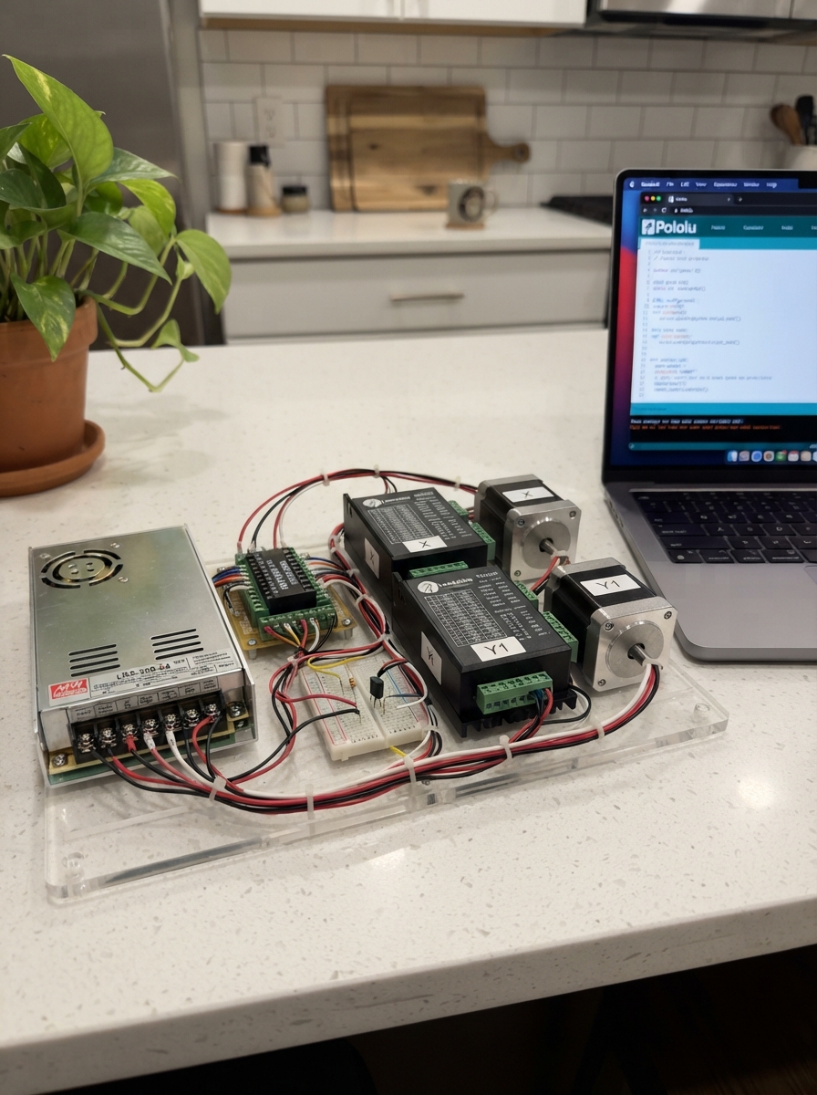
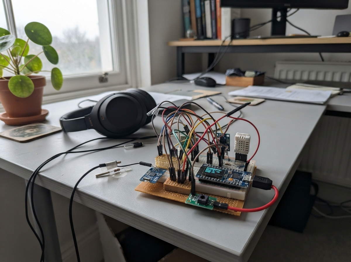
Photo of Smart IoT Safety Monitor
Generated with AI

Mahmoud Hatem

Published November 16, 2026

This smart safety monitor uses an ESP32 microcontroller to track environmental conditions and detect hazardous situations in real-time. It combines temperature and humidity sensing with door/window monitoring, infrared motion detection, and electrical current measurement to provide comprehensive safety oversight across a space.

The guide includes a complete wiring diagram, parts list, and step-by-step assembly instructions for integrating the DS18B20 temperature probe, DHT22 sensor, reed switch door alarm, current sensor, relay-controlled fan, and status indicators. The provided firmware handles sensor calibration, multi-sensor polling, and automated responses like triggering alarms or activating cooling systems based on detected conditions.

Wiring diagram

Loading diagram…

Gather all the parts

QtyComponent
1

DS18B20

Digital temperature sensor using OneWire protocol

1

DHT22

Digital temperature and humidity sensor

1

Resistor

4.7 kΩ

Through-hole resistor (current-limiting in series with an LED)

1

Resistor

4.7 kΩ

Through-hole resistor (current-limiting in series with an LED)

1

TCRT5000 module powered at 3.3 V

Catalog specification permits 3.3–5 V. AO unused.

1

TCRT5000 module powered at 3.3 V

Catalog specification permits 3.3–5 V. AO unused.

1

Reed Switch

Glass-encapsulated magnetic reed switch -- contacts close in the presence of a magnetic field. Standard door/window sensor for alarms. Wire as a digital input with internal pull-up; debounce in firmware.

1

ACS712 Current Sensor

Hall-effect AC/DC current sensor breakout. It outputs an analog voltage centered around VCC/2 at zero current; sensitivity depends on the 5 A, 20 A, or 30 A variant. Most modules run from 5 V and can output up to 5 V, so connect VIOUT to a 3.3 V MCU ADC through a divider or clamp.

1

10 kΩ passive voltage divider

10 kΩ

Passive resistor in ADC protection divider

1

15 kΩ passive voltage divider

15 kΩ

Passive resistor in ADC protection divider

1

LED

Red 5 mm

Standard 3mm/5mm through-hole LED. A current-limiting series resistor is added automatically.

1

Resistor

220 Ω

Through-hole resistor (current-limiting in series with an LED)

1

5 V active PCB buzzer

Chosen common active buzzer with built-in oscillator; maximum 30 mA for this base drive.

1

NPN Transistor (2N2222 / BC547)

2N2222

General-purpose NPN bipolar junction transistor (BJT) in TO-92 package. Used as a low-side switch to drive loads (e.g. buzzers) whose current exceeds ESP32 GPIO source capability (~12 mA). A ~1 kΩ base resistor is placed between the ESP32 GPIO and the transistor base. The collector connects to the load negative terminal (buzzer –), and the emitter connects to GND. When the GPIO goes HIGH (3.3 V), the transistor saturates and switches the load on. Compatible with both 2N2222/2N2222A and BC547/BC547B variants. Add a flyback diode (e.g. 1N4148) across inductive load terminals.

1

Resistor

1 kΩ

Through-hole resistor (current-limiting in series with an LED)

1

Resistor

10 kΩ

Through-hole resistor (current-limiting in series with an LED)

1

NPN Transistor (2N2222 / BC547)

2N2222

General-purpose NPN bipolar junction transistor (BJT) in TO-92 package. Used as a low-side switch to drive loads (e.g. buzzers) whose current exceeds ESP32 GPIO source capability (~12 mA). A ~1 kΩ base resistor is placed between the ESP32 GPIO and the transistor base. The collector connects to the load negative terminal (buzzer –), and the emitter connects to GND. When the GPIO goes HIGH (3.3 V), the transistor saturates and switches the load on. Compatible with both 2N2222/2N2222A and BC547/BC547B variants. Add a flyback diode (e.g. 1N4148) across inductive load terminals.

1

Resistor

1 kΩ

Through-hole resistor (current-limiting in series with an LED)

1

Resistor

10 kΩ

Through-hole resistor (current-limiting in series with an LED)

1

NPN Transistor (2N2222 / BC547)

2N2222

General-purpose NPN bipolar junction transistor (BJT) in TO-92 package. Used as a low-side switch to drive loads (e.g. buzzers) whose current exceeds ESP32 GPIO source capability (~12 mA). A ~1 kΩ base resistor is placed between the ESP32 GPIO and the transistor base. The collector connects to the load negative terminal (buzzer –), and the emitter connects to GND. When the GPIO goes HIGH (3.3 V), the transistor saturates and switches the load on. Compatible with both 2N2222/2N2222A and BC547/BC547B variants. Add a flyback diode (e.g. 1N4148) across inductive load terminals.

1

Resistor

1 kΩ

Through-hole resistor (current-limiting in series with an LED)

1

Resistor

10 kΩ

Through-hole resistor (current-limiting in series with an LED)

1

5 V single-channel active-low relay module

Common active-low module with onboard coil driver and flyback suppression. NPN pulls IN low to energize; GPIO HIGH means on.

1

Resistor

10 kΩ

Through-hole resistor (current-limiting in series with an LED)

1

5 V single-channel active-low relay module

Common active-low module with onboard coil driver and flyback suppression. NPN pulls IN low to energize; GPIO HIGH means on.

1

Resistor

10 kΩ

Through-hole resistor (current-limiting in series with an LED)

1

7025 12 V DC cooling fan

Two-wire fan; verify actual current on label before powering.

1

3–6 V geared DC motor

Two-terminal brushed geared motor; keep disabled until stall current and driver temperature verified.

1

IRLZ44N Logic-Level N-Channel MOSFET

Logic-level N-channel MOSFET commonly used as a low-side switch for DC loads from 3.3V or 5V microcontroller GPIO. Use a gate resistor, a gate pulldown, and a flyback diode for inductive loads.

1

Resistor

100 Ω

Through-hole resistor (current-limiting in series with an LED)

1

Resistor

10 kΩ

Through-hole resistor (current-limiting in series with an LED)

1

1N4007 Diode

General-purpose silicon rectifier diode in DO-204AL (DO-41) axial through-hole package. Rated 1A average forward current and 1000V peak reverse voltage (VRRM). Forward voltage drop ~0.7V at typical load (up to 1.1V at full 1A). Used here in series with LM7805 Vout for reverse polarity protection: anode to LM7805 output, cathode to 5V rail, resulting in ~4.3V on the output rail. Not suitable for high-frequency switching (reverse recovery ~2µs–30µs); intended for DC or 50/60Hz rectification only.

1

1N4007 Diode

General-purpose silicon rectifier diode in DO-204AL (DO-41) axial through-hole package. Rated 1A average forward current and 1000V peak reverse voltage (VRRM). Forward voltage drop ~0.7V at typical load (up to 1.1V at full 1A). Used here in series with LM7805 Vout for reverse polarity protection: anode to LM7805 output, cathode to 5V rail, resulting in ~4.3V on the output rail. Not suitable for high-frequency switching (reverse recovery ~2µs–30µs); intended for DC or 50/60Hz rectification only.

1

12 V 2 A isolated DC adapter with female DC connector

Use supplied low-voltage DC output only; verify connector polarity with a meter.

1

Electrolytic Capacitor

2200 µF 50 V

Radial aluminium electrolytic capacitor bought by value and voltage rating, such as 10 µF, 100 µF or 1000 µF 10 V. It is polarised: the + lead goes to the higher voltage and the - lead, marked by the stripe on the sleeve, to the lower voltage or ground. It is mostly used for bulk filtering across a power rail, with a voltage rating comfortably above the rail.

1

24v Buck Converter

LM2596-based adjustable step-down buck converter module. Commonly used to regulate a higher battery rail, such as a 2S 18650 pack, down to 5V for Arduino logic. It is a regulator, not a charger or battery protection board.

Assemble it in 6 steps

1. Check the power before connecting electronics

Use only the adapter's isolated DC output. Verify connector polarity. With electronics disconnected, adjust the LM2596 output to 5.0 V with a meter. Connect capacitor positive to 12 V and striped negative to GND. Connect the 5 V output to VIN, never 12 V. Join all grounds.

  • Reversing the capacitor can make it rupture. Disconnect power and discharge it before changing wires.
  • Do not simultaneously connect external 5 V VIN and USB 5 V. Deploy on USB with external VIN wire disconnected; for powered serial use a USB connection with its 5 V conductor disconnected.

2. Connect low-voltage sensors

Power both temperature sensors and IR modules from 3.3 V. Probe data goes to GPIO4 and DHT data to GPIO18, each with a 4.7 kΩ pull-up to 3.3 V. IR digital outputs go to GPIO13 and GPIO14; leave AO disconnected. Door contact goes between GPIO19 and GND. The magnet closes the contact.

  • Identify waterproof probe wires from their supplied labels, not color alone. IR output polarity depends on the board and target; serial prints raw levels.

3. Protect the analog input

ACS712 VCC to 5 V and GND to GND. Output through 10 kΩ to GPIO34; 15 kΩ from GPIO34 to GND. This limits a 5 V output to 3.0 V. Connect IP+ to 5 V and IP- to motor positive: only motor current is measured. Boot calibration requires motor OFF.

  • Never connect ACS712 output directly to the ESP32. ADC current is approximate; calibrate against a meter.

4. Wire the door alarm

GPIO32 through 220 Ω to red LED anode, cathode to GND. Active 5 V buzzer positive to 5 V, negative to 2N2222 collector. Emitter to GND, GPIO25 through 1 kΩ to base, 10 kΩ base to GND. Buzzer diode band to positive, other end to collector.

  • Added parts are required: two additional 2N2222 transistors and an additional 1N4007. Check actual transistor lead order; it differs between packages. Chosen buzzer is active, not passive, and must draw at most 30 mA.

5. Connect relay control and fan

For each active-low 5 V relay, use a 2N2222 interface: GPIO26 or GPIO27 through 1 kΩ to base; 10 kΩ base to ground; emitter to ground; collector to IN. Add 10 kΩ IN to 5 V. Relay VCC to 5 V and GND to ground. Relay1 COM to 12 V, NO to fan positive, fan negative to ground. Leave unused contacts disconnected. GPIO HIGH turns these interfaces on.

  • Use active-low modules with onboard coil protection. Verify relay action before attaching fan. These contacts switch low-voltage DC only, never mains.

6. Replace the undersized motor transistor

Use the added IRLZ44N: source to ground, drain to motor negative; GPIO33 through 100 Ω to gate and 10 kΩ gate to ground. Motor positive comes from ACS712 IP-. Flyback diode band to motor positive, anode to drain. Firmware leaves motor OFF because no motor behavior was requested.

  • The listed 2N2222 with 1 kΩ base drive is not a safe geared-motor driver. IRLZ44N performance at 3.3 V must be checked under the actual stall load; use a 3.3 V-rated motor driver if it heats. Do not enable motor until checked.
  • Adapter budget is 24 W total. Check fan starting current and motor stall current; LM2596 modules may need cooling well below advertised 3 A. Keep load power wiring off breadboard contacts; use secure terminal wiring.

Review all connections

1. Connections between "probe" and "ESP32"

FunctionprobeESP32
powerVCC3V3
groundGNDGND
dataDATAGPIO 4

2. Connections between "probe_pullup" and "ESP32"

Functionprobe_pullupESP32
digitalP1 → DS18B20 DATAEXT
powerP23V3

3. Connections between "dht" and "ESP32"

FunctiondhtESP32
powerVCC3V3
groundGNDGND
dataDATAGPIO 18

4. Connections between "dht_pullup" and "ESP32"

Functiondht_pullupESP32
digitalP1 → DHT22 DATAEXT
powerP23V3

5. Connections between "ir1" and "ESP32"

Functionir1ESP32
powerVCC3V3
groundGNDGND
digitalDOGPIO 13

6. Connections between "ir2" and "ESP32"

Functionir2ESP32
powerVCC3V3
groundGNDGND
digitalDOGPIO 14

7. Connections between "door" and "ESP32"

FunctiondoorESP32
dataPIN1GPIO 19
groundPIN2GND

8. Connections between "current" and "ESP32"

FunctioncurrentESP32
powerVCC5V
groundGNDGND
powerIP+5V
dataIP- → 3–6 V geared DC motor PLUSEXT

9. Connections between "adc_top" and "ESP32"

Functionadc_topESP32
analogA → ACS712 Current Sensor VIOUTEXT
analogBGPIO 34

10. Connections between "adc_bottom" and "ESP32"

Functionadc_bottomESP32
analogA → 10 kΩ passive voltage divider BEXT
groundBGND

11. Connections between "led" and "ESP32"

FunctionledESP32
groundGNDGND

12. Connections between "led_r" and "ESP32"

Functionled_rESP32
digitalP1GPIO 32
digitalP2 → LED ANODEEXT

13. Connections between "buzzer" and "ESP32"

FunctionbuzzerESP32
powerPLUS5V

14. Connections between "buzz_driver" and "ESP32"

Functionbuzz_driverESP32
groundEMITTERGND
digitalCOLLECTOR → 5 V active PCB buzzer MINUSEXT

15. Connections between "buzz_driver_base" and "ESP32"

Functionbuzz_driver_baseESP32
digitalP1GPIO 25
digitalP2 → NPN Transistor (2N2222 / BC547) BASEEXT

16. Connections between "buzz_driver_off" and "ESP32"

Functionbuzz_driver_offESP32
digitalP1 → NPN Transistor (2N2222 / BC547) BASEEXT
groundP2GND

17. Connections between "relay1_driver" and "ESP32"

Functionrelay1_driverESP32
groundEMITTERGND
digitalCOLLECTOR → 5 V single-channel active-low relay module INEXT

18. Connections between "relay1_driver_base" and "ESP32"

Functionrelay1_driver_baseESP32
digitalP1GPIO 26
digitalP2 → NPN Transistor (2N2222 / BC547) BASEEXT

19. Connections between "relay1_driver_off" and "ESP32"

Functionrelay1_driver_offESP32
digitalP1 → NPN Transistor (2N2222 / BC547) BASEEXT
groundP2GND

20. Connections between "relay2_driver" and "ESP32"

Functionrelay2_driverESP32
groundEMITTERGND
digitalCOLLECTOR → 5 V single-channel active-low relay module INEXT

21. Connections between "relay2_driver_base" and "ESP32"

Functionrelay2_driver_baseESP32
digitalP1GPIO 27
digitalP2 → NPN Transistor (2N2222 / BC547) BASEEXT

22. Connections between "relay2_driver_off" and "ESP32"

Functionrelay2_driver_offESP32
digitalP1 → NPN Transistor (2N2222 / BC547) BASEEXT
groundP2GND

23. Connections between "relay1" and "ESP32"

Functionrelay1ESP32
powerVCC5V
groundGNDGND
powerCOM12V
powerNO → 7025 12 V DC cooling fan PLUSEXT

24. Connections between "relay1_pullup" and "ESP32"

Functionrelay1_pullupESP32
digitalP1 → 5 V single-channel active-low relay module INEXT
powerP25V

25. Connections between "relay2" and "ESP32"

Functionrelay2ESP32
powerVCC5V
groundGNDGND

26. Connections between "relay2_pullup" and "ESP32"

Functionrelay2_pullupESP32
digitalP1 → 5 V single-channel active-low relay module INEXT
powerP25V

27. Connections between "fan" and "ESP32"

FunctionfanESP32
groundMINUSGND

28. Connections between "motor_driver" and "ESP32"

Functionmotor_driverESP32
groundSOURCEGND
dataDRAIN → 3–6 V geared DC motor MINUSEXT

29. Connections between "motor_gate" and "ESP32"

Functionmotor_gateESP32
digitalP1GPIO 33
digitalP2 → IRLZ44N Logic-Level N-Channel MOSFET GATEEXT

30. Connections between "motor_off" and "ESP32"

Functionmotor_offESP32
digitalP1 → IRLZ44N Logic-Level N-Channel MOSFET GATEEXT
groundP2GND

31. Connections between "motor_diode" and "ESP32"

Functionmotor_diodeESP32
powerCathode → 3–6 V geared DC motor PLUSEXT
powerAnode → 3–6 V geared DC motor MINUSEXT

32. Connections between "buzz_diode" and "ESP32"

Functionbuzz_diodeESP32
powerCathode → 5 V active PCB buzzer PLUSEXT
powerAnode → 5 V active PCB buzzer MINUSEXT

33. Connections between "adapter" and "ESP32"

FunctionadapterESP32
powerPLUS12V
groundMINUSGND

34. Connections between "cap" and "ESP32"

FunctioncapESP32
power+12V
ground-GND

35. Connections between "buck" and "ESP32"

FunctionbuckESP32
powerVIN+12V
groundVIN-GND
powerVOUT+5V
groundVOUT-GND
powerVOUT+VIN

Deploy the firmware

#include <Arduino.h>
#include <OneWire.h>
#include <DallasTemperature.h>
#include <DHT.h>
// Safe pin changes: GPIO5 -> 18 and GPIO12 -> 19 (boot straps avoided).
constexpr int PROBE=4, DHT_PIN=18, IR1=13, IR2=14, DOOR=19;
constexpr int ADC_PIN=34, LED_PIN=32, BUZZ=25, FAN=26, SPARE=27, MOTOR=33;
// NPN interfaces invert active-low relay inputs: GPIO HIGH energizes relay.
OneWire wire(PROBE);
DallasTemperature ds(&wire);
DHT dht(DHT_PIN,DHT22);
float zeroMv=1500; // overwritten at boot with motor OFF
uint32_t sampleAt=0, conversionAt=0, changedAt=0;
bool converting=false, rawDoor=true, doorOpen=true, fanOn=false;
float probeC=NAN;
float adcMv(){
  uint32_t sum=0;
  for(int i=0;i<64;i++) sum+=analogReadMilliVolts(ADC_PIN);
  return sum/64.0f;
}
void setup(){
  Serial.begin(115200);
  for(int p: {LED_PIN,BUZZ,FAN,SPARE,MOTOR}){
    digitalWrite(p,LOW); pinMode(p,OUTPUT);
  }
  pinMode(IR1,INPUT_PULLUP); pinMode(IR2,INPUT_PULLUP);
  pinMode(DOOR,INPUT_PULLUP); pinMode(ADC_PIN,INPUT);
  analogReadResolution(12); analogSetPinAttenuation(ADC_PIN,ADC_11db);
  ds.begin(); ds.setResolution(12); ds.setWaitForConversion(false);
  dht.begin();
  // Only motor current passes through ACS712. Motor MUST remain off here.
  delay(500); zeroMv=adcMv();
  rawDoor=doorOpen=digitalRead(DOOR); changedAt=millis();
  ds.requestTemperatures(); conversionAt=millis(); converting=true;
  sampleAt=millis();
  Serial.println("Test ready. Motor and spare relay remain OFF. ACS712 measures motor branch only.");
}
void loop(){
  uint32_t now=millis();
  // Door alarm responds independently of the two-second sensor report.
  bool reading=digitalRead(DOOR);
  if(reading!=rawDoor){rawDoor=reading; changedAt=now;}
  if(now-changedAt>=40) doorOpen=rawDoor;
  digitalWrite(LED_PIN,doorOpen); digitalWrite(BUZZ,doorOpen);
  if(converting && now-conversionAt>=750){
    float t=ds.getTempCByIndex(0);
    probeC=(t!=DEVICE_DISCONNECTED_C && t>=-55 && t<=125)?t:NAN;
    // Fail-safe cooling on missing probe; threshold exactly as requested.
    fanOn=isnan(probeC) || probeC>30.0f;
    digitalWrite(FAN,fanOn); converting=false;
  }
  if(now-sampleAt>=2000){
    sampleAt=now;
    float air=dht.readTemperature(), humidity=dht.readHumidity();
    // 10k/15k divider factor = 0.6; ACS712-5A sensitivity = 185mV/A.
    float current=(adcMv()-zeroMv)/(0.6f*185.0f);
    Serial.printf("DS18B20=%.2f C%s | DHT22=%.2f C %.1f %%RH%s | IR1 raw=%d IR2 raw=%d | Door=%s | Motor current=%.3f A | Fan=%s\n",
      probeC,isnan(probeC)?" [FAULT cooling ON]":"",air,humidity,
      (isnan(air)||isnan(humidity))?" [READ ERROR]":"",digitalRead(IR1),digitalRead(IR2),
      doorOpen?"OPEN":"CLOSED",current,fanOn?"ON":"OFF");
    ds.requestTemperatures(); conversionAt=millis(); converting=true;
  }
}

Remix this project

Make it yours in one click

Open a full copy of this project in your own Schematik workspace, diagram, code, parts, and assembly steps included. Swap the sensor, add features, or redesign the whole thing with AI. The author's original stays untouched.

Open in Schematik