On this page
The Schematik Starter Kit has two ways to measure distance. The HC-SR04 sends out a chirp too high for you to hear and waits for the echo, the way a bat finds a wall in the dark. The VL53L0X fires a pulse of invisible laser light and times how long it takes to bounce back.
Both tell your board how far away something is. They differ in range, size and the voltage they expect, and that last one matters on an ESP32.
The short answer
| HC-SR04 | VL53L0X | |
|---|---|---|
| How it measures | Sound at 40kHz, times the echo | Infrared laser at 940nm, times the light |
| Range | From 2cm to 450cm (kit version) | Up to 120cm, or 200cm in long range mode in the dark |
| Spread of the beam | Narrower, 15° | Wider, 25° |
| Supply | Kit version: 2.8V to 5.5V | Kit board: 3.3V to 5V |
| Pins you wire | Vcc, Trig, Echo, GND | VCC, GND, SDA, SCL (GPIO1 and XSHUT are optional) |
| Time per reading | At least 60ms apart | About 33ms by default |
| What throws it off | Small or uneven targets | Daylight and dark surfaces |
Pick the HC-SR04 when you need more than about a meter. Pick the VL53L0X when the sensor has to be tiny, or when you want fast readings up close.
Is the HC-SR04 safe on a 3.3V board?
The one in the kit is. The seller lists it with an RCWL-9610A chip, rated from 2.8V to 5.5V, and its Echo pin sends back the same voltage you power it with. Power it from 3V3 and Echo comes back at 3.3V, which the ESP32-S3 reads without any extra parts.
Other HC-SR04 boards are a different story. The HC-SR04 datasheet lists 5V as the working voltage, so on those boards Echo sends back 5V. The ESP32-S3 datasheet puts the most a pin can take at 3.6V (the board's 3.3V plus 0.3V), and its pins are not built for 5V. Feeding 5V into a pin can damage the chip. If you're not sure which board you have, power it from 5V and use the divider further down.
Wiring the HC-SR04 to the ESP32-S3
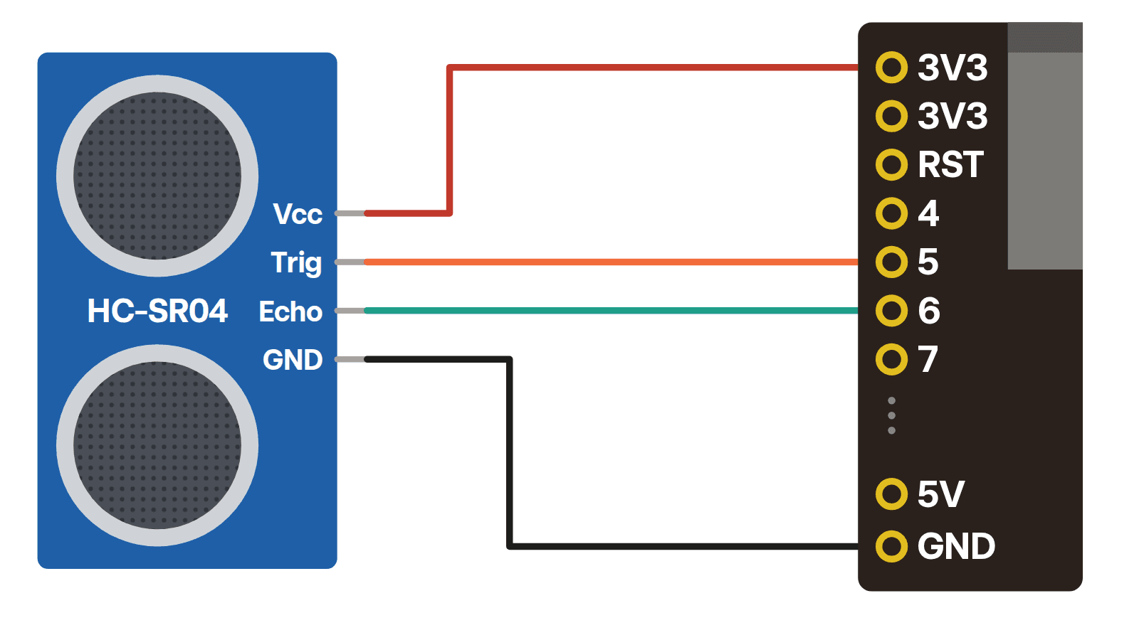
The diagram at the top shows the kit's HC-SR04 on the kit ESP32-S3 board, with the pin labels printed on the board:
| HC-SR04 pin | Board pin | What it does |
|---|---|---|
| Vcc | 3V3 | Powers the sensor at 3.3V |
| Trig | 5 | A short pulse from the board starts a reading |
| Echo | 6 | Stays high for as long as the sound took to come back |
| GND | GND | GND (ground) is the return path for the current |
No resistors needed at 3.3V.
If your HC-SR04 needs 5V
Move Vcc to the board's 5V pin and put a voltage divider between Echo and pin 6. A divider is two resistors in a row that share out the voltage, so the pin in the middle only sees part of it. The kit's resistors make a good one: 1kΩ from Echo to the pin, then two 1kΩ resistors in a row from the pin to GND.
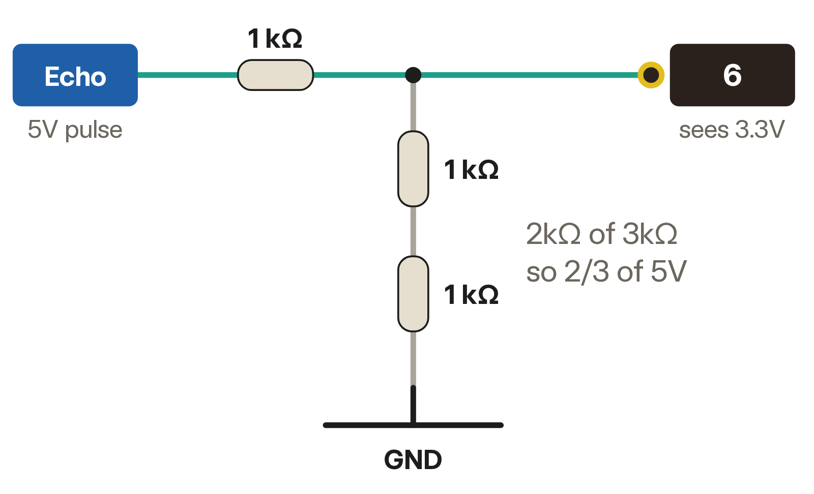
The pin gets the share that sits across the bottom 2kΩ:
pin 6 = 5V × 2kΩ ÷ (1kΩ + 2kΩ) ≈ 3.3V
That is above the roughly 2.5V the ESP32-S3 needs to read a pin as high, and below its 3.6V limit. Three 10kΩ resistors in the same pattern give the same 3.3V. Avoid 220Ω over 1kΩ: that leaves about 4.1V, still too high.
Trig can stay wired straight to pin 5. The datasheet asks for a TTL pulse, and TTL counts anything above 2V as high, so the board's 3.3V pulse starts a reading.
Wiring the VL53L0X to the ESP32-S3
The VL53L0X talks over I2C, a two-wire connection many sensors and screens share. SDA carries the data and SCL carries the clock that keeps both sides in step.
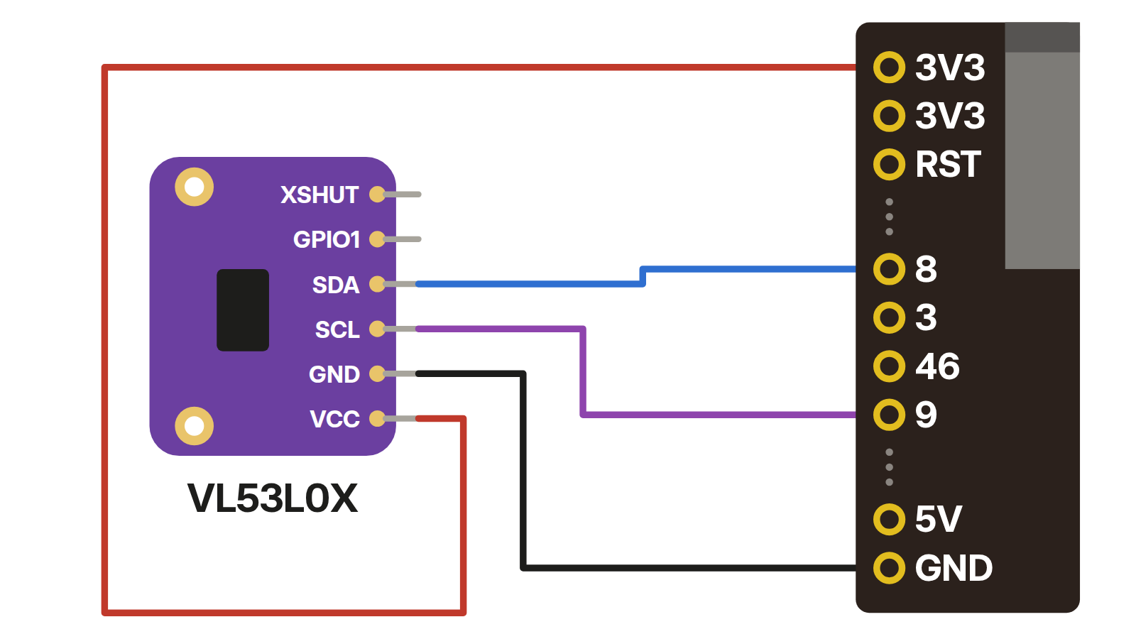
Power it from 3V3 so SDA and SCL never go above 3.3V. You can leave XSHUT and GPIO1 unconnected. XSHUT turns the sensor off, which helps when you run more than one on the same wires, and GPIO1 can tell the board a reading is ready. The sensor answers at I2C address 0x29.
Code: read both sensors at once
This sketch prints both distances side by side in the Serial Monitor. It uses the Adafruit VL53L0X library and works with the ESP32-S3 Arduino core, version 2 or 3.
#include <Arduino.h>
#include <Wire.h>
#include <Adafruit_VL53L0X.h>

const int TRIG = 5;
const int ECHO = 6;

Adafruit_VL53L0X lox;
bool loxReady = false;

void setup() {
  Serial.begin(115200);
  pinMode(TRIG, OUTPUT);
  pinMode(ECHO, INPUT);
  Wire.begin(8, 9);
  loxReady = lox.begin();
  if (!loxReady) {
    Serial.println("VL53L0X not found. Check SDA and SCL.");
  }
}

void loop() {
  digitalWrite(TRIG, LOW);
  delayMicroseconds(2);
  digitalWrite(TRIG, HIGH);
  delayMicroseconds(10);
  digitalWrite(TRIG, LOW);
  long echoTime = pulseIn(ECHO, HIGH, 30000);

  Serial.print("HC-SR04: ");
  if (echoTime > 0) {
    Serial.print(echoTime / 58.0, 1);
    Serial.print(" cm");
  } else {
    Serial.print("no echo");
  }

  Serial.print("   VL53L0X: ");
  VL53L0X_RangingMeasurementData_t measure;
  if (loxReady && lox.rangingTest(&measure, false) == VL53L0X_ERROR_NONE && measure.RangeStatus == 0) {
    Serial.print(measure.RangeMilliMeter / 10.0, 1);
    Serial.println(" cm");
  } else {
    Serial.println("no reading");
  }
  delay(100);
}
The HC-SR04 part starts with a 10 microsecond pulse on Trig. The sensor sends a short burst of 40kHz sound and holds Echo high until the sound comes back. Sound covers a centimeter there and back in about 58 microseconds, so dividing the time by 58 gives centimeters. That is the formula from the datasheet.
pulseIn gives up after 30,000 microseconds, the echo time for something about 5 meters away, and returns 0. The sketch prints "no echo" then. The VL53L0X part asks the sensor for one reading in millimeters. It prints the distance only when the read worked and RangeStatus is 0, the sensor's code for a good measurement.
Which one should I use?
Use the HC-SR04 for a parking sensor or anything a meter or more away. Its datasheet rates it on flat targets of at least half a square meter, so a wall or a car works better than a pencil.
Use the VL53L0X when space is tight or you want fast, close readings: a hand waving over a gadget, a robot that stops before the edge of the desk, a box that knows when its lid opens. Outdoors on an overcast day its range drops to between 60cm and 80cm on a white target.
Build it in Schematik
Open Schematik and describe what you want. It picks the parts, wires them and writes the code. Try one of these with the kit:
- "Show the distance from the HC-SR04 on the OLED screen in big numbers."
- "Chirp a passive buzzer faster as my hand gets closer to the VL53L0X."
- "A parking sensor: green LED far away, yellow closer, red when I should stop."
The ESP32 ultrasonic parking sensor is a full build you can open and remix.
FAQ
Can I power the HC-SR04 from 3.3V? The kit's version, yes: the seller rates it from 2.8V to 5.5V. Boards rated for 5V only need 5V and a divider on Echo.
Do I need a level shifter for the VL53L0X? Not when you power it from 3V3. The seller rates the board for 3.3V to 5V on both power and signals.
Why does my HC-SR04 always read 0? The board heard no echo within 30,000 microseconds. Check that Trig and Echo aren't swapped and that the sensor faces something flat.
Why does the VL53L0X say it isn't found? The board can't see it on I2C. Check that SDA goes to pin 8, SCL to pin 9 and VCC to 3V3.
Keep building from here
Jump into a step-by-step build, or open Schematik and turn your own idea into code, wiring, and assembly instructions.
Related posts
New to Hardware? A Beginner ESP32 Guide for Your First Build
A beginner ESP32 hardware guide: what to buy first, how breadboards work, what pin labels mean, and what to check before powering your first build.
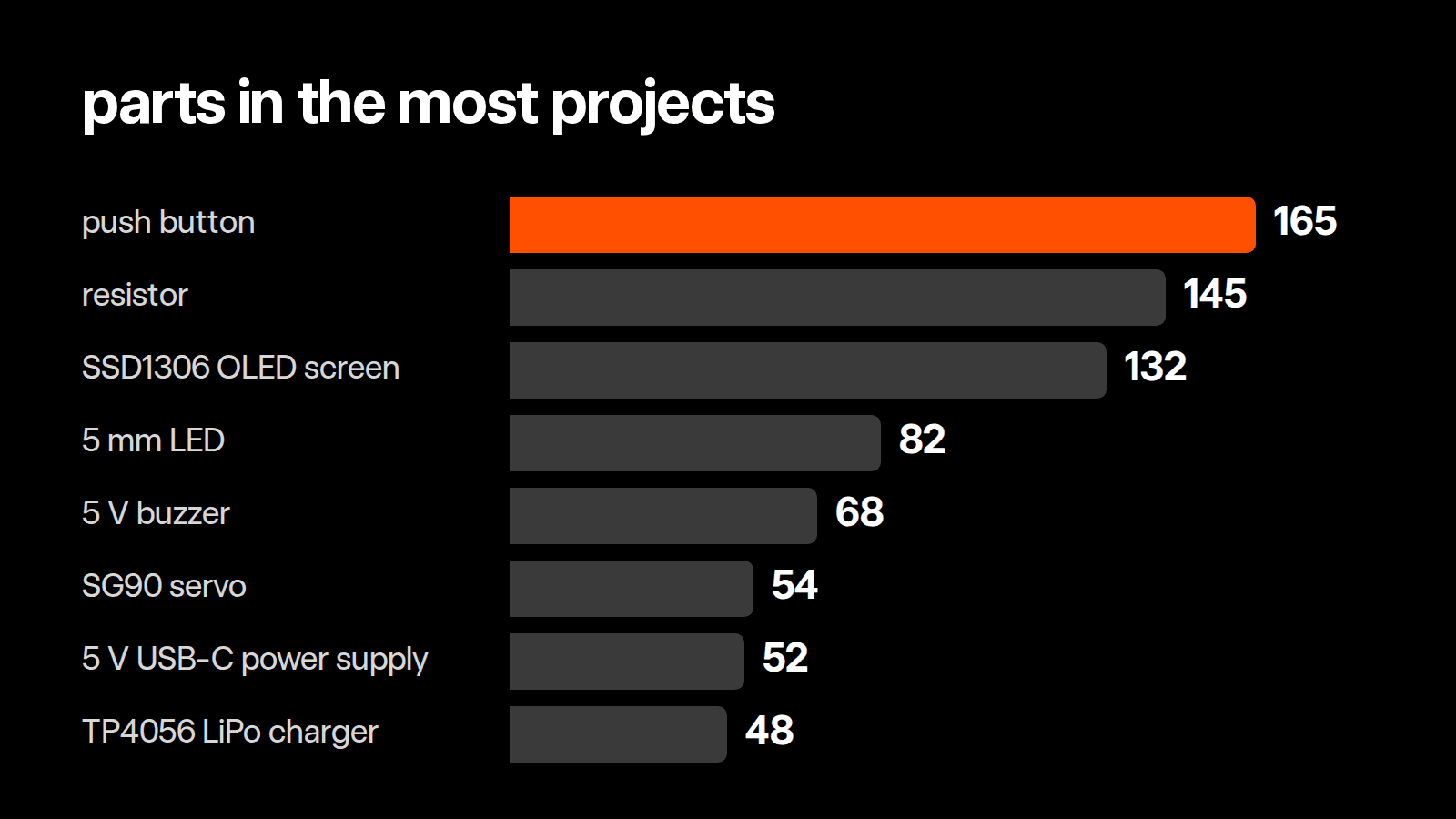
Most-used parts in Schematik projects
We counted the parts in all 902 published Schematik projects. A push button beat every screen and sensor, and one project in six adds no parts at all.
Related builds
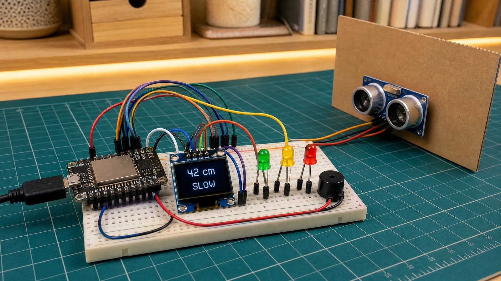
How to Build an ESP32 Ultrasonic Parking Sensor
Build a bench-safe ESP32 parking sensor with an HC-SR04P ultrasonic module, SSD1306 OLED, three warning LEDs, and a passive buzzer.
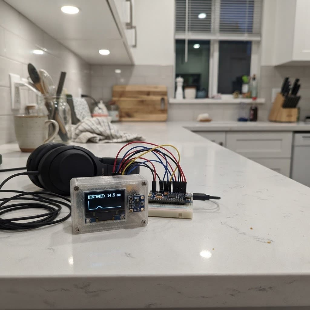
ToF Distance Monitor
Build a distance sensor with Arduino Uno and VL53L0X ToF sensor. Wiring, code, and assembly guide included.
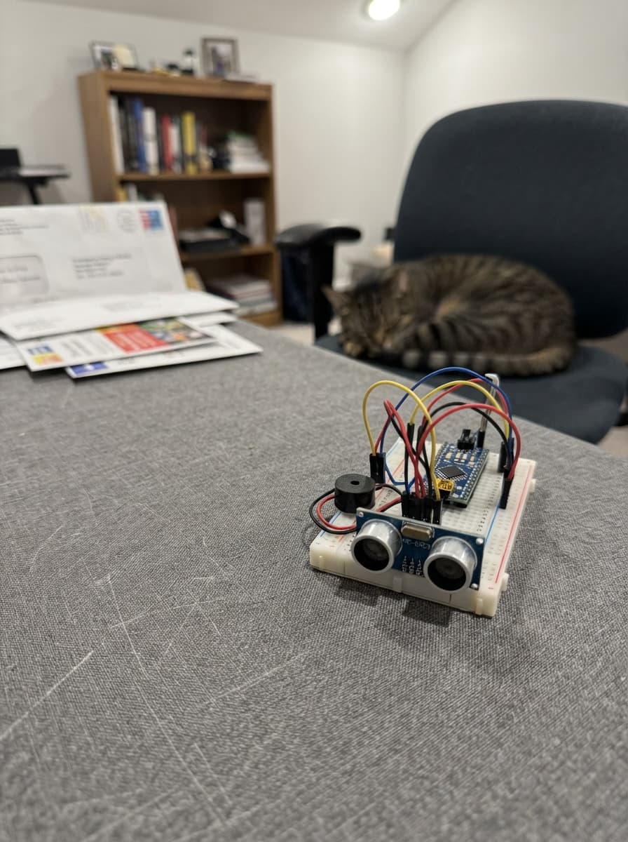
Ultrasonic Distance Alarm
Build an ultrasonic distance alarm with Arduino Uno, HC-SR04 sensor, and buzzer. Detect nearby objects with audio and visual alerts.