On this page
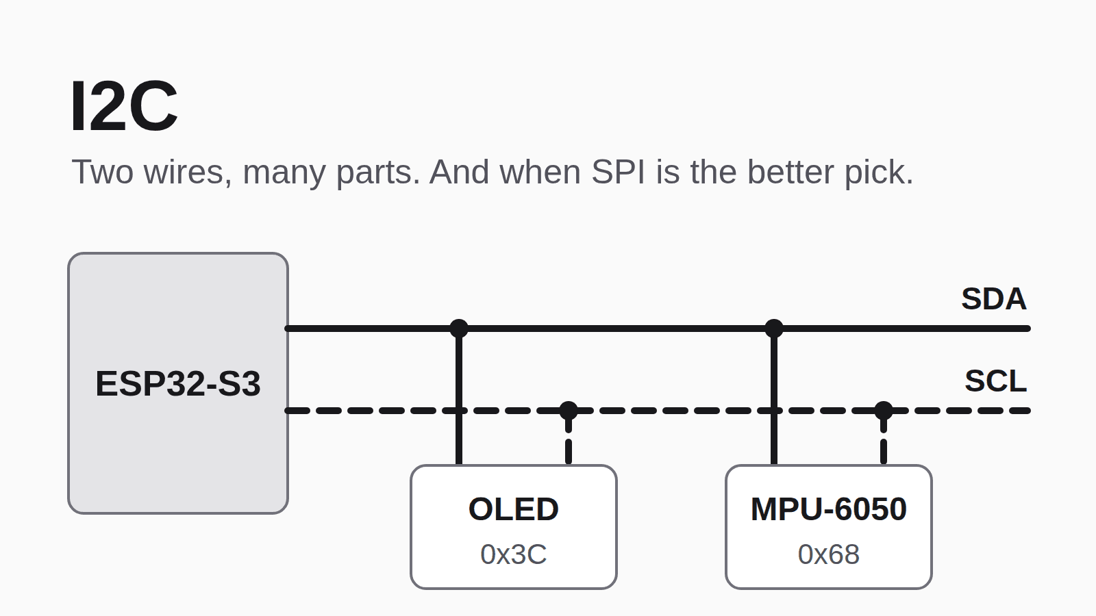
Plug a small OLED screen and an MPU-6050 motion sensor into an ESP32-S3, and both of them talk to the board over the same 2 wires. The screen draws your text, the sensor reports every tilt, and neither one gets confused by the other's messages.
That trick is I2C (say "I squared C"). Philips designed it in 1982 so chips on the same circuit board could talk without a tangle of wires, and it's still how the OLED and motion sensor in the Schematik Starter Kit talk to the board.
What is I2C?
I2C is a way for a board and its parts to share 2 wires:
- SDA (serial data) carries the data, in both directions.
- SCL (serial clock) carries the clock, a steady tick that tells every part when to read the next bit.
One device runs the conversation. NXP's I2C specification calls it the controller, and on your desk that's the ESP32-S3. Every other part on the wires is a target. A target only speaks when the controller asks it something.
Each part also needs power and ground, so a typical I2C module has 4 pins: VCC, GND, SDA and SCL.
How two parts share the same wires
Each part has an address that works like a name. On the parts in this guide it's a 7-bit number, so 7 ones and zeros, and it's usually written in hexadecimal, the base-16 numbers that start with 0x. The controller starts each message by calling out an address, and only the part with that name answers.
| Part | I2C address | Can you change it? |
|---|---|---|
| SSD1306 OLED screen | 0x3C | Yes, to 0x3D, with an address pin on the screen chip |
| MPU-6050 motion sensor | 0x68 | Yes, to 0x69, by pulling its AD0 pin high |
Those addresses come straight from the SSD1306 and MPU-6050 datasheets. Because they're different, the 2 parts can sit on the same SDA and SCL wires.
A 7-bit address gives 128 combinations. The I2C specification reserves 16 of them for special jobs, which leaves 112 for parts like yours.
What one I2C message looks like
Here's the ESP32-S3 sending one command to the OLED. Data travels in bytes, groups of 8 bits.
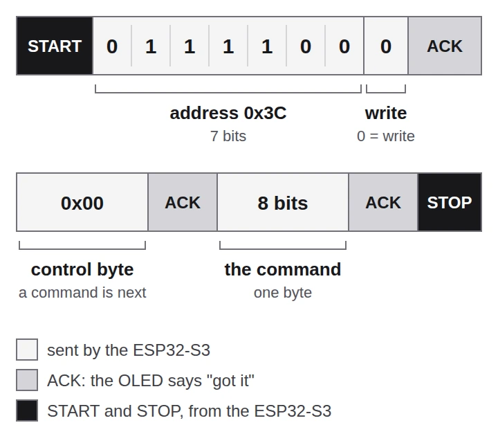
- START. The ESP32-S3 pulls SDA low while SCL is still high. Every part on the bus wakes up and listens.
- Address. It sends
0111100, which is0x3C, one bit per clock tick. - Read or write. One more bit:
0means "I'm going to write to you",1means "send me something". - ACK. The OLED recognizes its own address and pulls SDA low for one tick. That's its "got it". The MPU-6050 stays quiet because the message isn't for it.
- Control byte. The ESP32-S3 sends
0x00, which tells the SSD1306 that a command comes next. The OLED sends another ACK. - Command. One more byte, the command itself, and one more ACK.
- STOP. SDA goes high while SCL is high, and the bus is free again.
If no ACK comes back, nothing answered at that address. That's how an I2C scanner finds your parts.
Why I2C needs pull-up resistors
The kit wires its I2C bus the standard way, with open-drain outputs. That means no part on it drives a wire high. Each one can only pull SDA or SCL down to ground, or let go.
A pull-up resistor between each wire and 3.3V does the other half of the job. When every part lets go, the resistor brings the wire back up to high. With open-drain parts like these, the I2C specification calls for a pull-up on each line.
This is also why 2 open-drain parts can never fight over the wires. If both pull low at once, the wire is low, and nothing gets damaged.
Breakout boards can carry these resistors themselves, so check your board's schematic before adding more. The ESP32-S3 has its own built-in pull-ups too, but at 45kΩ they're weak, so a bus that relies on them alone runs slowly or not at all. Pull-up resistors have plenty of other jobs too, like keeping a button pin from floating.
Wire it up on an ESP32-S3
The Arduino core's generic ESP32-S3 board setting uses GPIO8 for SDA and GPIO9 for SCL by default. The Schematik Starter Kit example projects pick those 2 pins on purpose with Wire.begin(8, 9), so they work whichever board setting you choose.
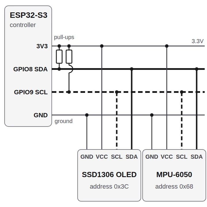
| ESP32-S3 pin | SSD1306 OLED | MPU-6050 (GY-521) |
|---|---|---|
3V3 | VCC | VCC |
GND | GND | GND |
GPIO8 | SDA | SDA |
GPIO9 | SCL | SCL |
Both parts land on the same 2 pins. On a breadboard, run SDA and SCL along 2 rows and plug both modules into them.
To check that both parts answer, this short I2C scanner prints every address that replies:
#include <Wire.h>

void setup() {
  Serial.begin(115200);
  Wire.begin(8, 9);  // SDA, SCL
}

void loop() {
  for (uint8_t address = 1; address < 127; address++) {
    Wire.beginTransmission(address);
    if (Wire.endTransmission() == 0) {
      Serial.printf("Found a part at 0x%02X\n", address);
    }
  }
  Serial.println("Scan done");
  delay(5000);
}
Open the Serial Monitor at 115200 baud. Every 5 seconds, with the wiring above, you should see 0x3C and 0x68.
If the scanner finds nothing, check these 2 things first:
- SDA and SCL swapped. Swap the 2 wires and run it again.
- Missing ground. Every part needs a
GNDwire back to the board.
Two parts on the same address are harder to spot, because both answer at once and the scanner prints one address. Move one of them with its address pin, or put it on the ESP32-S3's second I2C controller on 2 other pins.
How fast is I2C?
The I2C specification defines a few speed modes:
| Mode | Top speed |
|---|---|
| Standard-mode | 100 kbit/s |
| Fast-mode | 400 kbit/s |
| Fast-mode Plus | 1 Mbit/s |
| High-speed mode | 3.4 Mbit/s |
Your parts set the real limit. The MPU-6050 and the SSD1306 both top out at Fast-mode, 400kHz. The ESP32-S3 datasheet lists its own I2C controllers at up to 800 kbit/s, depending on how strong the pull-up resistors are.
That's plenty for a sensor that sends a few numbers 100 times a second, or a 128×64 pixel screen. It gets tight for anything that moves a lot of data.
SPI vs I2C
SPI (serial peripheral interface) is the other common way parts talk to a board. It trades wires for speed.
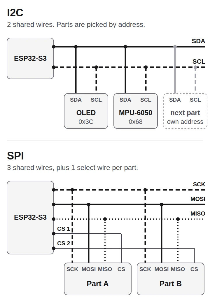
SPI has 3 shared wires and one extra wire per part:
- SCK is the clock.
- MOSI carries data from the controller out to the part.
- MISO carries data from the part back in to the controller.
- CS (chip select) is a separate wire for each part. The controller pulls one CS low, and only that part listens.
Because data goes out and comes back on separate wires, SPI can send and receive at the same time.
| I2C | SPI | |
|---|---|---|
| Signal wires | 2, shared by every part | 3 shared, plus 1 CS per part |
| How a part is picked | 7-bit address in the message | Its own CS wire |
| Data direction | One way at a time on SDA | Both ways at once (MOSI and MISO) |
| Typical speed | 100 or 400 kbit/s | Several MHz and up |
| ESP32-S3 limit | 800 kbit/s | 80MHz as controller |
| Needs pull-ups | Yes | No |
| Kit example | OLED, MPU-6050 | 8×8 LED matrix (MAX7219) |
The 8×8 LED matrix in the starter kit uses a MAX7219 driver chip, which takes SPI-style data at up to 10MHz. It only ever listens, so nothing comes back on MISO. Its DIN, CLK and CS pins line up with MOSI, SCK and CS. It runs on 5V, and its datasheet only promises to read a HIGH above 3.5V, which is more than an ESP32-S3 pin puts out. A level shifter between them closes that gap.
When to use SPI instead of I2C
Pick I2C when:
- you have several sensors that each send a few bytes at a time
- you're short on free pins, since 10 parts still only need 2 signal wires
- your part only talks I2C, like the kit's 4-pin OLED and the MPU-6050
Pick SPI when:
- the part moves a lot of data, like a color TFT screen or a microSD card
- you need fast updates, such as a screen that redraws many times a second
- two parts are stuck on the same I2C address and one of them also comes in an SPI version
Plenty of projects use both: an I2C sensor or two on GPIO8 and GPIO9, and an SPI screen on its own pins.
Build something with an I2C bus
The self-balancing rover puts this exact pair on one I2C bus. An MPU-6050 measures the tilt, and an SSD1306 OLED shows the angle while the rover keeps itself upright. It runs on a classic ESP32, so its I2C pins are GPIO21 and GPIO22. Open it in Schematik to get the wiring, the parts list and the code, then press Deploy.
For a calmer first build, the CO2 room monitor shares one I2C bus between an SSD1306 OLED and an SCD41 CO2 sensor, on the same classic ESP32 pins.
Once both parts answer the scanner, try this: tilt the MPU-6050 and print the angle on the OLED. That's 2 parts, 2 wires and one tiny spirit level.
Keep building from here
Jump into a step-by-step build, or open Schematik and turn your own idea into code, wiring, and assembly instructions.
Related posts
Related builds
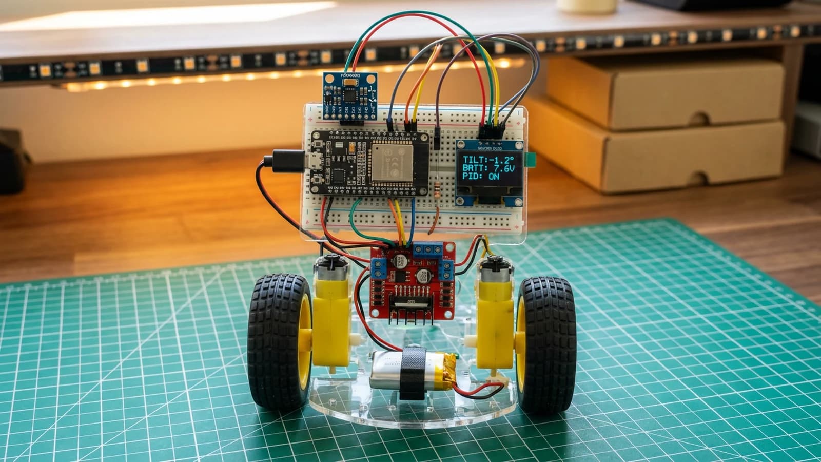
How to Build a Self-Balancing Rover with ESP32
Build an ESP32 self-balancing mini rover with MPU6050 IMU, OLED display, and PID control. Complete guide with wiring, code, and assembly.
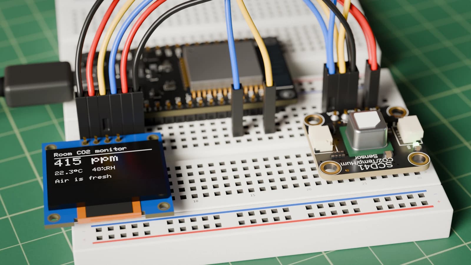
How to Build a CO2 Room Monitor with ESP32
Build an ESP32 CO2 monitor with an Adafruit SCD41 sensor, SSD1306 OLED, shared I2C wiring, warning thresholds, and live temperature and humidity readings.