Community project
8-Channel AES3 Distribution Amplifier
Tammo Buhren
Published August 10, 2026 · Updated August 11, 2026
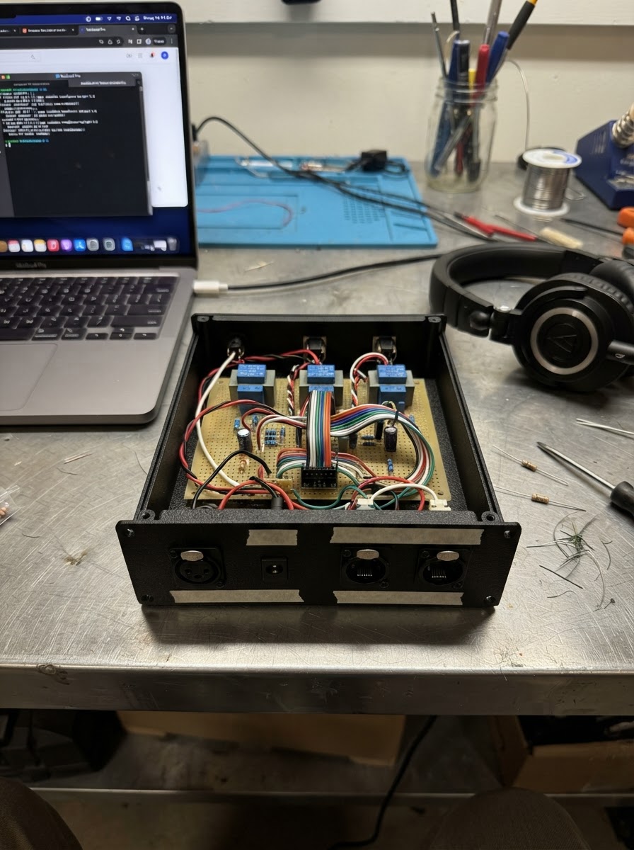
Generated with AIThis 8-channel AES3 distribution amplifier takes a single AES3 digital audio input and distributes it to two independent outputs, each carrying all eight channels. Built around isolation transformers and shielded connectors, the amplifier maintains signal integrity across professional audio installations while rejecting common-mode interference.
The guide provides a complete parts list, wiring diagram, and step-by-step assembly instructions for building the amplifier in a metal enclosure. The AES3 signal path is entirely passive and transformer-based, requiring only a 5 V DC power input for the ESP32 controller. Assembly proceeds from preparing the enclosure through fitting input and output stages, with a final inspection and single-link test before full deployment.
Wiring diagram

Interactive · read-only
Pan and zoom to explore the wiring. Remix the project to edit it in your own workspace.
Parts list
Bill of materials| Component | Qty | Notes |
|---|---|---|
| Shielded RJ45 input connectorShielded panel RJ45 | 1 | A metal-shielded eight-pin panel connector that receives all four balanced AES3 links. |
| Shielded RJ45 output connector AShielded panel RJ45 | 1 | A metal-shielded eight-pin panel connector carrying the first isolated copy of all four AES3 links. |
| Shielded RJ45 output connector BShielded panel RJ45 | 1 | A metal-shielded eight-pin panel connector carrying the second isolated copy of all four AES3 links. |
| Locking 5 V DC panel inputLocking 5 V DC connector | 1 | A panel connector that accepts power from the certified external 5 volt supply. |
| 110 ohm AES3 1:1 input isolation transformer1:1, 110 Ω AES3 rated | 1 | An isolation transformer for AES3 link 1, carrying audio channels 1 and 2. |
| 110 ohm AES3 1:1 input isolation transformer1:1, 110 Ω AES3 rated | 1 | An isolation transformer for AES3 link 2, carrying audio channels 3 and 4. |
| 110 ohm AES3 1:1 input isolation transformer1:1, 110 Ω AES3 rated | 1 | An isolation transformer for AES3 link 3, carrying audio channels 5 and 6. |
| 110 ohm AES3 1:1 input isolation transformer1:1, 110 Ω AES3 rated | 1 | An isolation transformer for AES3 link 4, carrying audio channels 7 and 8. |
| 110 ohm AES3 1:1 output isolation transformer — Output A channels 1–21:1, 110 Ω AES3 rated | 1 | An AES3-rated transformer that isolates the first balanced output link on Output A. |
| 110 ohm AES3 1:1 output isolation transformer — Output A channels 3–41:1, 110 Ω AES3 rated | 1 | An AES3-rated transformer that isolates the second balanced output link on Output A. |
| 110 ohm AES3 1:1 output isolation transformer — Output A channels 5–61:1, 110 Ω AES3 rated | 1 | An AES3-rated transformer that isolates the third balanced output link on Output A. |
| 110 ohm AES3 1:1 output isolation transformer — Output A channels 7–81:1, 110 Ω AES3 rated | 1 | An AES3-rated transformer that isolates the fourth balanced output link on Output A. |
| 110 ohm AES3 1:1 output isolation transformer — Output B channels 1–21:1, 110 Ω AES3 rated | 1 | An AES3-rated transformer that isolates the first balanced output link on Output B. |
| 110 ohm AES3 1:1 output isolation transformer — Output B channels 3–41:1, 110 Ω AES3 rated | 1 | An AES3-rated transformer that isolates the second balanced output link on Output B. |
| 110 ohm AES3 1:1 output isolation transformer — Output B channels 5–61:1, 110 Ω AES3 rated | 1 | An AES3-rated transformer that isolates the third balanced output link on Output B. |
| 110 ohm AES3 1:1 output isolation transformer — Output B channels 7–81:1, 110 Ω AES3 rated | 1 | An AES3-rated transformer that isolates the fourth balanced output link on Output B. |
| THVD1452 50 Mb/s full-duplex RS-422 transceiver — receiver 150 Mb/s, 5 V | 1 | A high-speed 5 volt differential interface chip used only to receive the channels 1–2 AES3 link. |
| THVD1452 50 Mb/s full-duplex RS-422 transceiver — receiver 250 Mb/s, 5 V | 1 | A high-speed 5 volt differential interface chip used only to receive the channels 3–4 AES3 link. |
| THVD1452 50 Mb/s full-duplex RS-422 transceiver — receiver 350 Mb/s, 5 V | 1 | A high-speed 5 volt differential interface chip used only to receive the channels 5–6 AES3 link. |
| THVD1452 50 Mb/s full-duplex RS-422 transceiver — receiver 450 Mb/s, 5 V | 1 | A high-speed 5 volt differential interface chip used only to receive the channels 7–8 AES3 link. |
| THVD1452 high-speed RS-422 driver — Output A link 1high-speed 5 V RS-422 | 1 | A 5 volt high-speed differential driver that sends the channels 1–2 AES3 link to Output A. |
| THVD1452 high-speed RS-422 driver — Output A link 2high-speed 5 V RS-422 | 1 | A 5 volt high-speed differential driver that sends the channels 3–4 AES3 link to Output A. |
| THVD1452 high-speed RS-422 driver — Output A link 3high-speed 5 V RS-422 | 1 | A 5 volt high-speed differential driver that sends the channels 5–6 AES3 link to Output A. |
| THVD1452 high-speed RS-422 driver — Output A link 4high-speed 5 V RS-422 | 1 | A 5 volt high-speed differential driver that sends the channels 7–8 AES3 link to Output A. |
| THVD1452 high-speed RS-422 driver — Output B link 1high-speed 5 V RS-422 | 1 | A 5 volt high-speed differential driver that sends the channels 1–2 AES3 link to Output B. |
| THVD1452 high-speed RS-422 driver — Output B link 2high-speed 5 V RS-422 | 1 | A 5 volt high-speed differential driver that sends the channels 3–4 AES3 link to Output B. |
| THVD1452 high-speed RS-422 driver — Output B link 3high-speed 5 V RS-422 | 1 | A 5 volt high-speed differential driver that sends the channels 5–6 AES3 link to Output B. |
| THVD1452 high-speed RS-422 driver — Output B link 4high-speed 5 V RS-422 | 1 | A 5 volt high-speed differential driver that sends the channels 7–8 AES3 link to Output B. |
| 74AHCT244 octal buffer — four AES3 link fan-outSOIC-20, 5 V | 1 | A fast 5 volt logic buffer that makes two separate copies of each of the four recovered AES3 signals. |
| Resistor110 Ω, 1%, 0603 | 1 | Through-hole resistor (current-limiting in series with an LED) |
| Resistor110 Ω, 1%, 0603 | 1 | Through-hole resistor (current-limiting in series with an LED) |
| Resistor110 Ω, 1%, 0603 | 1 | Through-hole resistor (current-limiting in series with an LED) |
| Resistor110 Ω, 1%, 0603 | 1 | Through-hole resistor (current-limiting in series with an LED) |
Assembly
7 stepsPrepare the metal enclosure
Use a metal rack enclosure with three shielded RJ45 panel cut-outs marked INPUT, OUTPUT A, and OUTPUT B, plus one locking 5 V DC input cut-out. Bond each RJ45 metal shell directly to the enclosure with a short, wide connection; this gives cable noise a safe path to the chassis.
- Tip: Mark every RJ45 port “AES3 ONLY — NOT ETHERNET — NO PoE” before fitting it.
- ⚠ Do not connect these ports to an Ethernet switch or PoE injector; that can damage the distribution amplifier and connected audio equipment.
Fit the input side parts
Fit the four input transformers beside the INPUT connector. Keep each transformer close to its matching RJ45 pair: pins 1–2 for link 1, pins 3–6 for link 2, pins 4–5 for link 3, and pins 7–8 for link 4. Fit each 110 Ω 1% resistor directly across that transformer’s receiver-side pair.
- Tip: Keep the two copper tracks of each pair the same length and route them next to one another.
- ⚠ Do not substitute Ethernet magnetics for the AES3 transformers; the wrong transformer can distort the digital-audio signal.
Fit the receiver and copying stage
Fit the four receiver ICs and the 74AHCT244 copying buffer near the input transformers. Add a 100 nF ceramic capacitor from 5 V to ground at every IC supply pin pair, placed as close to the chip as possible.
- Tip: The buffer makes one separate electrical copy for Output A and another for Output B; it does not decode or alter the audio.
- ⚠ Keep the input transformer secondary tracks short; long tracks can pick up noise and cause dropouts.
Fit the Output A path
Fit Output A’s four driver ICs and four output transformers between the copying buffer and the OUTPUT A connector. Route the transformer secondaries to pins 1–2, 3–6, 4–5, and 7–8 in that order.
- Tip: Keep every outgoing pair as a 110 Ω differential pair and avoid branches or unused trace stubs.
- ⚠ Swapping the plus and minus wires of one pair reverses that AES3 link and may prevent the receiving equipment from locking.
Fit the Output B path
Fit Output B’s four driver ICs and four output transformers in the same way. Route the output transformer secondaries to pins 1–2, 3–6, 4–5, and 7–8 on OUTPUT B.
- Tip: Output A and Output B must remain separate after the copying buffer so a fault or unplugged cable on one output does not load the other.
- ⚠ Never join an Output A pair directly to the same Output B pair; the two outputs must be separately driven and transformer-isolated.
Wire and protect the 5 V input
Bring the certified regulated 5 V supply into the locking DC connector, then route it through reverse-polarity and over-current protection before the 5 V plane. Connect its return to the circuit ground plane; do not use the RJ45 signal pairs as power or ground wires.
- Tip: Use a supply rated for at least 1 A even though the circuit draws less; it will run cooler and has margin.
- ⚠ Check the connector polarity with a meter before plugging in the board—reversed 5 V power can damage every interface chip.
Inspect and test one link first
Before connecting studio equipment, check for shorts between 5 V and ground. Then connect a known AES3 source to INPUT and a known AES3 receiver to Output A using the correct shielded 110 Ω cable. Verify channels 1–2 first, then repeat for the other three pairs and Output B.
- Tip: If one pair fails, first check the pin pair order: 1–2, 3–6, 4–5, then 7–8.
- ⚠ Power down before changing soldered connections; accidental shorts can damage the drivers or connected audio hardware.
Pin assignments
Board wiring reference| Pin | Connection | Type |
|---|---|---|
| 5V | dc_input +5V | power |
| GND | dc_input GND | ground |
| EXT | rj45_in 1 → 110 ohm AES3 1:1 input isolation transformer PRI+ | data |
| EXT | rj45_in 2 → 110 ohm AES3 1:1 input isolation transformer PRI- | data |
| EXT | rj45_in 3 → 110 ohm AES3 1:1 input isolation transformer PRI+ | data |
| EXT | rj45_in 6 → 110 ohm AES3 1:1 input isolation transformer PRI- | data |
| EXT | rj45_in 4 → 110 ohm AES3 1:1 input isolation transformer PRI+ | data |
| EXT | rj45_in 5 → 110 ohm AES3 1:1 input isolation transformer PRI- | data |
| EXT | rj45_in 7 → 110 ohm AES3 1:1 input isolation transformer PRI+ | data |
| EXT | rj45_in 8 → 110 ohm AES3 1:1 input isolation transformer PRI- | data |
| EXT | rj45_in SHELL → earthed metal enclosure | ground |
| EXT | rj45_out_a SHELL → earthed metal enclosure | ground |
| EXT | rj45_out_b SHELL → earthed metal enclosure | ground |
| EXT | in_tx1 SEC+ → THVD1452 50 Mb/s full-duplex RS-422 transceiver — receiver 1 IN+ | data |
| EXT | in_tx1 SEC- → THVD1452 50 Mb/s full-duplex RS-422 transceiver — receiver 1 IN- | data |
| EXT | term1 P1 → THVD1452 50 Mb/s full-duplex RS-422 transceiver — receiver 1 IN+ | digital |
| EXT | term1 P2 → THVD1452 50 Mb/s full-duplex RS-422 transceiver — receiver 1 IN- | digital |
| EXT | in_tx2 SEC+ → THVD1452 50 Mb/s full-duplex RS-422 transceiver — receiver 2 IN+ | data |
| EXT | in_tx2 SEC- → THVD1452 50 Mb/s full-duplex RS-422 transceiver — receiver 2 IN- | data |
| EXT | term2 P1 → THVD1452 50 Mb/s full-duplex RS-422 transceiver — receiver 2 IN+ | digital |
| EXT | term2 P2 → THVD1452 50 Mb/s full-duplex RS-422 transceiver — receiver 2 IN- | digital |
| EXT | in_tx3 SEC+ → THVD1452 50 Mb/s full-duplex RS-422 transceiver — receiver 3 IN+ | data |
| EXT | in_tx3 SEC- → THVD1452 50 Mb/s full-duplex RS-422 transceiver — receiver 3 IN- | data |
| EXT | term3 P1 → THVD1452 50 Mb/s full-duplex RS-422 transceiver — receiver 3 IN+ | digital |
| EXT | term3 P2 → THVD1452 50 Mb/s full-duplex RS-422 transceiver — receiver 3 IN- | digital |
| EXT | in_tx4 SEC+ → THVD1452 50 Mb/s full-duplex RS-422 transceiver — receiver 4 IN+ | data |
| EXT | in_tx4 SEC- → THVD1452 50 Mb/s full-duplex RS-422 transceiver — receiver 4 IN- | data |
| EXT | term4 P1 → THVD1452 50 Mb/s full-duplex RS-422 transceiver — receiver 4 IN+ | digital |
| EXT | term4 P2 → THVD1452 50 Mb/s full-duplex RS-422 transceiver — receiver 4 IN- | digital |
| EXT | rx_link1 OUT → 74AHCT244 octal buffer — four AES3 link fan-out IN1 | digital |
| EXT | rx_link2 OUT → 74AHCT244 octal buffer — four AES3 link fan-out IN2 | digital |
| EXT | rx_link3 OUT → 74AHCT244 octal buffer — four AES3 link fan-out IN3 | digital |
| EXT | rx_link4 OUT → 74AHCT244 octal buffer — four AES3 link fan-out IN4 | digital |
| EXT | drv_a1 OUT+ → 110 ohm AES3 1:1 output isolation transformer — Output A channels 1–2 PRI+ | data |
| EXT | drv_a1 OUT- → 110 ohm AES3 1:1 output isolation transformer — Output A channels 1–2 PRI- | data |
| EXT | drv_a2 OUT+ → 110 ohm AES3 1:1 output isolation transformer — Output A channels 3–4 PRI+ | data |
| EXT | drv_a2 OUT- → 110 ohm AES3 1:1 output isolation transformer — Output A channels 3–4 PRI- | data |
| EXT | drv_a3 OUT+ → 110 ohm AES3 1:1 output isolation transformer — Output A channels 5–6 PRI+ | data |
| EXT | drv_a3 OUT- → 110 ohm AES3 1:1 output isolation transformer — Output A channels 5–6 PRI- | data |
| EXT | drv_a4 OUT+ → 110 ohm AES3 1:1 output isolation transformer — Output A channels 7–8 PRI+ | data |
| EXT | drv_a4 OUT- → 110 ohm AES3 1:1 output isolation transformer — Output A channels 7–8 PRI- | data |
| EXT | drv_b1 OUT+ → 110 ohm AES3 1:1 output isolation transformer — Output B channels 1–2 PRI+ | data |
| EXT | drv_b1 OUT- → 110 ohm AES3 1:1 output isolation transformer — Output B channels 1–2 PRI- | data |
| EXT | drv_b2 OUT+ → 110 ohm AES3 1:1 output isolation transformer — Output B channels 3–4 PRI+ | data |
| EXT | drv_b2 OUT- → 110 ohm AES3 1:1 output isolation transformer — Output B channels 3–4 PRI- | data |
| EXT | drv_b3 OUT+ → 110 ohm AES3 1:1 output isolation transformer — Output B channels 5–6 PRI+ | data |
| EXT | drv_b3 OUT- → 110 ohm AES3 1:1 output isolation transformer — Output B channels 5–6 PRI- | data |
| EXT | drv_b4 OUT+ → 110 ohm AES3 1:1 output isolation transformer — Output B channels 7–8 PRI+ | data |
| EXT | drv_b4 OUT- → 110 ohm AES3 1:1 output isolation transformer — Output B channels 7–8 PRI- | data |
| EXT | out_tx_a1 SEC+ → Shielded RJ45 output connector A 1 | data |
| EXT | out_tx_a1 SEC- → Shielded RJ45 output connector A 2 | data |
| EXT | out_tx_a2 SEC+ → Shielded RJ45 output connector A 3 | data |
| EXT | out_tx_a2 SEC- → Shielded RJ45 output connector A 6 | data |
| EXT | out_tx_a3 SEC+ → Shielded RJ45 output connector A 4 | data |
| EXT | out_tx_a3 SEC- → Shielded RJ45 output connector A 5 | data |
| EXT | out_tx_a4 SEC+ → Shielded RJ45 output connector A 7 | data |
| EXT | out_tx_a4 SEC- → Shielded RJ45 output connector A 8 | data |
| EXT | out_tx_b1 SEC+ → Shielded RJ45 output connector B 1 | data |
| EXT | out_tx_b1 SEC- → Shielded RJ45 output connector B 2 | data |
| EXT | out_tx_b2 SEC+ → Shielded RJ45 output connector B 3 | data |
| EXT | out_tx_b2 SEC- → Shielded RJ45 output connector B 6 | data |
| EXT | out_tx_b3 SEC+ → Shielded RJ45 output connector B 4 | data |
| EXT | out_tx_b3 SEC- → Shielded RJ45 output connector B 5 | data |
| EXT | out_tx_b4 SEC+ → Shielded RJ45 output connector B 7 | data |
| EXT | out_tx_b4 SEC- → Shielded RJ45 output connector B 8 | data |
| 5V | rx_link1 VCC | power |
| GND | rx_link1 GND | ground |
| 5V | rx_link2 VCC | power |
| GND | rx_link2 GND | ground |
| 5V | rx_link3 VCC | power |
| GND | rx_link3 GND | ground |
| 5V | rx_link4 VCC | power |
| GND | rx_link4 GND | ground |
| 5V | logic_fanout VCC | power |
| GND | logic_fanout GND | ground |
| 5V | drv_a1 VCC | power |
| GND | drv_a1 GND | ground |
| 5V | drv_a2 VCC | power |
| GND | drv_a2 GND | ground |
| 5V | drv_a3 VCC | power |
| GND | drv_a3 GND | ground |
| 5V | drv_a4 VCC | power |
| GND | drv_a4 GND | ground |
| 5V | drv_b1 VCC | power |
| GND | drv_b1 GND | ground |
| 5V | drv_b2 VCC | power |
| GND | drv_b2 GND | ground |
| 5V | drv_b3 VCC | power |
| GND | drv_b3 GND | ground |
| 5V | drv_b4 VCC | power |
| GND | drv_b4 GND | ground |
| EXT | logic_fanout A1 → THVD1452 high-speed RS-422 driver — Output A link 1 IN | digital |
| EXT | logic_fanout A2 → THVD1452 high-speed RS-422 driver — Output A link 2 IN | digital |
| EXT | logic_fanout A3 → THVD1452 high-speed RS-422 driver — Output A link 3 IN | digital |
| EXT | logic_fanout A4 → THVD1452 high-speed RS-422 driver — Output A link 4 IN | digital |
| EXT | logic_fanout B1 → THVD1452 high-speed RS-422 driver — Output B link 1 IN | digital |
| EXT | logic_fanout B2 → THVD1452 high-speed RS-422 driver — Output B link 2 IN | digital |
| EXT | logic_fanout B3 → THVD1452 high-speed RS-422 driver — Output B link 3 IN | digital |
| EXT | logic_fanout B4 → THVD1452 high-speed RS-422 driver — Output B link 4 IN | digital |
Firmware
ESP32// Hardware-only AES3 distribution amplifier.
// The AES3 signal path is entirely discrete: no ESP32 GPIO is used.
void setup() {}
void loop() {}“Deploy to device” opens this project in Schematik, where you can flash it to your board over USB.
Remix this project
Make it yours in one click
Open a full copy of this project in your own Schematik workspace — diagram, code, parts, and assembly steps included. Swap the sensor, add features, or redesign the whole thing with AI. The author's original stays untouched.